GnrlPatton
New Member
- Joined
- Sep 23, 2020
- Messages
- 8
I read through this thread: https://diysolarforum.com/threads/custom-bus-bars-from-copper-flat-bar.33832/
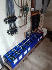
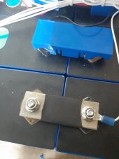
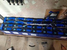
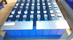
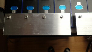
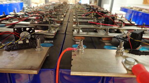
But my situation is a little different. I'm going to be building my pack in a 3p4s configuration (I have 12x 304aH cells and am configuring it for 12v). It will be going in my boat, once I build out a case for it of plywood and cement board. The cells I got don't have enough bus bars to connect them in the configuration I'm planning on, which is this:

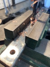
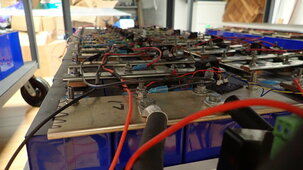
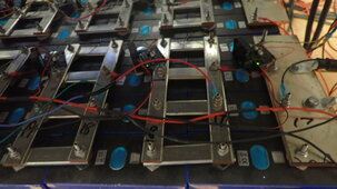
So, I'm looking at building them myself. I was considering building them from lengths of cable and crimping lugs on, but I'm not sure if I have enough post to do that, plus attach the BMS leads. So I was considering buying flat copper bar, cutting it to length for each of the bars pictured (5 total) and then drilling out for the posts. Reading through the post mentioned above, I'll have to figure a way to get them drilled accurately, which I can do with my drill press I think.
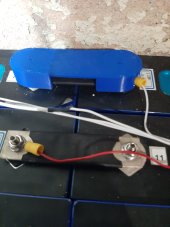
I am planning on building into the case a way to compress the cells so they don't move, but I'm wondering what the thoughts from this group would be on having the solid bars connecting cells? Would having them in a boat, with potential movement, risk the posts with movement (they are welded posts, with about 3/8" available thread)? Am I better off just building the cable based bus bars so there's flexibility, and then trying to find thin enough lugs to be able to work with the available thread?
Thanks for any input,
Kevin
But my situation is a little different. I'm going to be building my pack in a 3p4s configuration (I have 12x 304aH cells and am configuring it for 12v). It will be going in my boat, once I build out a case for it of plywood and cement board. The cells I got don't have enough bus bars to connect them in the configuration I'm planning on, which is this:
So, I'm looking at building them myself. I was considering building them from lengths of cable and crimping lugs on, but I'm not sure if I have enough post to do that, plus attach the BMS leads. So I was considering buying flat copper bar, cutting it to length for each of the bars pictured (5 total) and then drilling out for the posts. Reading through the post mentioned above, I'll have to figure a way to get them drilled accurately, which I can do with my drill press I think.
I am planning on building into the case a way to compress the cells so they don't move, but I'm wondering what the thoughts from this group would be on having the solid bars connecting cells? Would having them in a boat, with potential movement, risk the posts with movement (they are welded posts, with about 3/8" available thread)? Am I better off just building the cable based bus bars so there's flexibility, and then trying to find thin enough lugs to be able to work with the available thread?
Thanks for any input,
Kevin