diy solar

diy solar

DIY Fuse Holders and Distribution Busbars

ArthurEld

Solar Wizard
Joined
Aug 3, 2020
Messages
2,298
Location
Palm Harbor, Florida
I would like to make some fuse holders and distribution busbars.

Does anyone know where to buy the plastic (or what it is called) that is used to make the base that gets screwed down?
I assume it is fire resistant and won't melt easy.

I assume wood isn't advisable. I don't remember seeing anyone using wood.

I didn't see much discussion about this subject and I am not sure if I am putting this in the right place.

If anyone has helpful links or low cost ideas please share
 
  • Like
Reactions: Dzl
I would like to make some fuse holders and distribution busbars.

Does anyone know where to buy the plastic (or what it is called) that is used to make the base that gets screwed down?
I assume it is fire resistant and won't melt easy.
I don't, but I'm also curious for the same as well as other purposes.

I assume wood isn't advisable. I don't remember seeing anyone using wood.
I would assume not, it briefly crossed my mind that a dense hardwood might work okay. But I don't like the idea of wood when there are certainly more suitable non-conductive heat and fire resistant options out there.
 
I believe the material is phenolic sheeting you may be looking for.
 
  • Like
Reactions: Dzl
Try these insulating standoffs:


Something like that came with the busbar that I bought. There was an aluminum foot in addition for more height, but I guess you could use a stud to stack two of these standoffs.

Here's mine; you can see one of the standoffs.
My ground busbar is on the bottom, and fuse holders for positive are secured to it.

 
Same ones I used hedge. On my 3/8 copper buss bars , to insulator, to aluminum plate. Nice units
 
Try these insulating standoffs:


Something like that came with the busbar that I bought. There was an aluminum foot in addition for more height, but I guess you could use a stud to stack two of these standoffs.

Here's mine; you can see one of the standoffs.
My ground busbar is on the bottom, and fuse holders for positive are secured to it.

I could use the two 3/4 OD standoffs to create a 100A class T fuse holder. Bolt each side of the fuse and a lug to the standoff.
I would have to come up with a cover.

I could also make busbars of any size with 2 standoffs and a piece of copper bar

I could attach the standoffs to my fixture or to a piece of the composite material or wood.
 
Last edited:
I could use the two 3/4 OD standoffs to create a 100A class T fuse holder. Bolt each side of the fuse and a lug to the standoff.
I would have to come up with a cover.

Ceramic standoff - be careful about what torque it can take. Look up specs for class-T fuse holders to see how much you want.
A stud with nut on bottom could let you torque just the electrical joint, so long as you don't get careless.
The glass reinforced plastic with metal inserts are more likely to be strong enough, but then size could be an issue.

I've considered cables bolted directly to fuses.

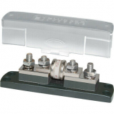
I bought Blue Sea fuse holders ($46 each) for my batteries. These have a snap-on plastic cover that is impossible to get off without breaking something.
They have another model with latches that might be better.

1612224416318.png


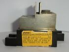
For my utility disconnect, I bought Bussman class-T holders ($24 per pair used) because they are UL listed. There are two lengths of class-T fuses, depending on voltage. The shorter fuse holder was hard to come by. the Bussman holders are two halves, can be bolted to a structure to implement either size. They have exposed metal heatsinks and dual screw terminals.

1612224450523.png
 
I would like to make some fuse holders and distribution busbars.

Does anyone know where to buy the plastic (or what it is called) that is used to make the base that gets screwed down?
I assume it is fire resistant and won't melt easy.

I assume wood isn't advisable. I don't remember seeing anyone using wood.

I didn't see much discussion about this subject and I am not sure if I am putting this in the right place.

If anyone has helpful links or low cost ideas please share

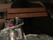
So, here is my DIY bus/distro bar approach, would love to hear some feedback. Picture below of components.

2x 12” x 1/8” x 1 1/2” copper bars
2x packages of 1 pair (red and black) distribution terminals.

I will cut the bars in 1/2 and double them up. The distribution terminals are for me to mount the copper bars to, which then can be secured to a plywood board.

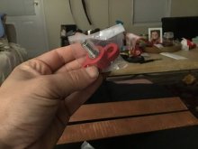
I opened on of the packages of distribution terminals to be able to get a better picture of what they are.

I bought this all off Amazon along with several 3/8” studs to slip through holes drilled into the bars for connection terminals.

Question: can I attach wiring/ring terminals both above and beneath the bars? i.e. one stud having cable attached on both the top and bottom of the bus bars (e.g. 2 separate mppt controller outputs, 1 attached on top and the other on bottom).
 

Attachments

  • 46B72577-1F81-46CB-99B5-AE5DF39C3E02.jpeg
    46B72577-1F81-46CB-99B5-AE5DF39C3E02.jpeg
    48.7 KB · Views: 48
  • B54EB8BE-2388-4A06-930E-F31E91C3B708.jpeg
    B54EB8BE-2388-4A06-930E-F31E91C3B708.jpeg
    51.6 KB · Views: 48
I will cut the bars in 1/2 and double them up. The distribution terminals are for me to mount the copper bars to, which then can be secured to a plywood board.

Why? You wished you had 1/4" thick bars?

First I would consider the multiple inputs and outputs going on the busbar, see if an arrangement reduces current though any point of busbar in half.
Could also consider folding into a square box, so current flows both directions.

Question: can I attach wiring/ring terminals both above and beneath the bars? i.e. one stud having cable attached on both the top and bottom of the bus bars (e.g. 2 separate mppt controller outputs, 1 attached on top and the other on bottom).

Sure, that's what I did. Battery negative went on top of busbar to middle hole. Two inverter/charger cables went top/bottom on the left, and two went top/bottom on the right.
 
Why? You wished you had 1/4" thick bars?

First I would consider the multiple inputs and outputs going on the busbar, see if an arrangement reduces current though any point of busbar in half.
Could also consider folding into a square box, so current flows both directions.


Sure, that's what I did. Battery negative went on top of busbar to middle hole. Two inverter/charger cables went top/bottom on the left, and two went top/bottom on the right.
No, just like the idea of over building. Now I don’t remember what the ampacity of the 1/8“ x 1 1/2” copper was when I originally spec’d this out, but I know it was enough to handle the load for a samlex EVO 4024 inverter/charger. Do you think doubling it (to 1/4”) would be absurd overkill? If so, i’ll either leave them 12” and have plenty of room for expansion, or still 1/2 them and have an extra set of +- bus bars for a future project.
 
I certainly would not make a fuse holder with wood near any of the conducting parts, but I would be OK with using wood for a busbar standoff.

busbar <not equal to> conducting parts ?

Oh, "fuse holder with wood near any of the conducting parts" as in fuse running hot, making the wood toasty?
 
Ceramic standoff - be careful about what torque it can take. Look up specs for class-T fuse holders to see how much you want.
A stud with nut on bottom could let you torque just the electrical joint, so long as you don't get careless.
The glass reinforced plastic with metal inserts are more likely to be strong enough, but then size could be an issue.

I've considered cables bolted directly to fuses.

I bought Blue Sea fuse holders ($46 each) for my batteries. These have a snap-on plastic cover that is impossible to get off without breaking something.
They have another model with latches that might be better.

View attachment 35527
I have that one but I want to use 100A class T fuses for my batteries.

I plan to use that big one between my multi battery busbar and my on/off switch
For my utility disconnect, I bought Bussman class-T holders ($24 per pair used) because they are UL listed. There are two lengths of class-T fuses, depending on voltage. The shorter fuse holder was hard to come by. the Bussman holders are two halves, can be bolted to a structure to implement either size. They have exposed metal heatsinks and dual screw terminals.


View attachment 35528

I would like something like those. Sadly my batteries will never be UL listed.
Do you think a heat sink is necessary for a fuse holder?
 
Do you think doubling it (to 1/4”) would be absurd overkill?
No, but be aware that double busbars is not as good as one bus-bar with the same thickness as the two combined.
busbar <not equal to> conducting parts ?

Oh, "fuse holder with wood near any of the conducting parts" as in fuse running hot, making the wood toasty?
Yes.... or even a blowing fuse. Properly chosen fuses should not get hot enough for a fire but with the kind of amperage we deal with in our projects I just don't want to risk it.

However, I would be OK with wood standoffs for busbars but part of my system bring-up is to check for anything running warm when under full load.

Yes.... my logic between the two cases probably does not hold water...... ;)
 
  • Like
Reactions: Dzl
No, just like the idea of over building. Now I don’t remember what the ampacity of the 1/8“ x 1 1/2” copper was when I originally spec’d this out, but I know it was enough to handle the load for a samlex EVO 4024 inverter/charger. Do you think doubling it (to 1/4”) would be absurd overkill?

1/8“ x 1 1/2” = 0.1875 in^2 = 121 mm^2
Compare to 4/0 cable, 107 mm^2 allowed 405A in free air or 260A in bundle of 3.
Your flat conductor has more surface area, too.

Is EVO 4024 4000W at 24V, 167A?
 
So, here is my DIY bus/distro bar approach, would love to hear some feedback. Picture below of components.

2x 12” x 1/8” x 1 1/2” copper bars
2x packages of 1 pair (red and black) distribution terminals.

I will cut the bars in 1/2 and double them up. The distribution terminals are for me to mount the copper bars to, which then can be secured to a plywood board.

I opened on of the packages of distribution terminals to be able to get a better picture of what they are.

I bought this all off Amazon along with several 3/8” studs to slip through holes drilled into the bars for connection terminals.

Question: can I attach wiring/ring terminals both above and beneath the bars? i.e. one stud having cable attached on both the top and bottom of the bus bars (e.g. 2 separate mppt controller outputs, 1 attached on top and the other on bottom).
I like that
 
Back
Top