diy solar

diy solar

DIY Grid Tie Without Batteries

Valid concern. It looks like the growatt and mpp inverters someone else posted here will do grid sharing where they draw from the grid when pv power gets too low.
Any grid tied inverter operating in parallel with the grid does that. The only limit on power supply is the supply panel breaker's rating.

Some inverters which operate in series with the grid can blend the power sources of PV and grid, but only up to the output limit of the inverter.
 
Any grid tied inverter operating in parallel with the grid does that. The only limit on power supply is the supply panel breaker's rating.

Some inverters which operate in series with the grid can blend the power sources of PV and grid, but only up to the output limit of the inverter.
Maybe I am dumb. Please explain ‘in series with the grid’ In my simple mind when you put two generating devices in series the output voltage is the sum of the two or does your ‘series‘ mean something different ? The Growatt 5000 ES can supply the load from any combination of sources : battery + solar + grid = total load , depending on settings. We call it ‘blending’.
 
Maybe I am dumb. Please explain ‘in series with the grid’ In my simple mind when you put two generating devices in series the output voltage is the sum of the two or does your ‘series‘ mean something different ? The Growatt 5000 ES can supply the load from any combination of sources : battery + solar + grid = total load , depending on settings. We call it ‘blending’.
That one went right over my head as well......been doing commercial electric since ‘66 and I havent heard of “ in series with the grid”
 
That one went right over my head as well......been doing commercial electric since ‘66 and I havent heard of “ in series with the grid”
I agree Dave. a Lot of terms on this forum are used very loosely , in conflict with accepted terms used in electronic / electrical engineering.
 
Its tough for me, 21 years at General Electric, if we said something like that we would be over knocking at the door of Westinghouse
 
Maybe I am dumb. Please explain ‘in series with the grid’ In my simple mind when you put two generating devices in series the output voltage is the sum of the two or does your ‘series‘ mean something different ? The Growatt 5000 ES can supply the load from any combination of sources : battery + solar + grid = total load , depending on settings. We call it ‘blending’.
I agree Dave. a Lot of terms on this forum are used very loosely , in conflict with accepted terms used in electronic / electrical engineering.
I agree it's not a good use of the term.

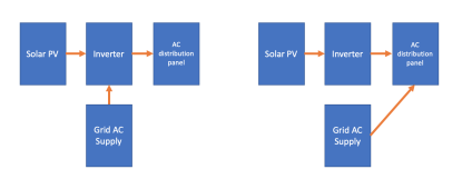
What I mean is probably more easily explained by a pic:

Screen Shot 2022-01-01 at 7.46.59 pm.png
In the set up on the left the supply to the AC distribution panel is limited by the solar PV inverter's output.
This is how my off-grid system works when I'm operating in grid backup mode.

In the set up on the right the inverter and the grid operate in parallel and the supply is not limited by the solar PV inverter.
This is how my grid tied system operates.
 
Correct on the GroWatts. As I stated before. I don't know if the MPP can do that or not. Maybe Ian at Watts247 can step in and answer that question on the MPP.
they can.. my 8000 max can, but it is quite unless without a small battery
 
I agree it's not a good use of the term.

What I mean is probably more easily explained by a pic:


In the set up on the left the supply to the AC distribution panel is limited by the solar PV inverter's output.
This is how my off-grid system works when I'm operating in grid backup mode.

What this picture could represent is grid charging battery and all AC output coming from inverter.
Or, inverter has a relay feeding grid through to AC distribution panel (like a UPS) but also adding power.

If grid only charges battery, I would call that an "On-line UPS"

In the set up on the right the inverter and the grid operate in parallel and the supply is not limited by the solar PV inverter.
This is how my grid tied system operates.

Like PowerWall or Sunny Boy Storage shifting peaks by adding AC power some times of the day.
 
Being grid tied of course the arrays are producing the maximum they can at any given moment, but it does highlight challenges of managing when output capacity is so variable.
In reality this is a problem that is so easily to fix if we don't confine ourselves to conventional thinking. Op will get his battery less system up and running and be able to refute the next news item proclaiming solar causing grid instability!

'Being grid tied of course the arrays are producing the maximum they can at any given moment,' .....more of a scheduling problem caused by invested asset owners not wanting to be the one to lose out!
My 12v system, is now so stable with the help of a few items from aliexpress that a few months ago I finally disconnected my long expired lead acid batteries with no problems, Supercaps, extra diversion loads, and the final fix of a relay that cuts off pv input to 2 PWMs at 14.9v.
My PV's voltage range is limited, 20VOC, so the final solution is infrequent, and will allow an infinite number of extra panels in //.

What I am trying to say is - If I can do it- anyone can - the principles the same irrespective of complexity.
 
What this picture could represent is grid charging battery and all AC output coming from inverter.
Or, inverter has a relay feeding grid through to AC distribution panel (like a UPS) but also adding power.

If grid only charges battery, I would call that an "On-line UPS"
In my case, my off-grid system has various modes of operation which determines what charges the battery. Can be solar or grid.

Like PowerWall or Sunny Boy Storage shifting peaks by adding AC power some times of the day.
Yes, although my grid tied system doesn't have a battery.

It's a bit trickier for me as my home has 3-phase supply. Battery systems which are approved for grid-tied operation here cost a fortune and are not worth it. Hence why mine is off-grid.

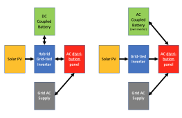
If I ever did get a grid-tied battery, I can go with either of these options:
Screen Shot 2022-01-02 at 9.48.47 am.png
But because I am 3-phase, only the DC-coupled hybrid option would enable the solar PV system to operate during a grid outage as well as supply all phases.

In the AC coupled arrangement backup is confined to that phase only and is limited to the capacity stored in the battery at the time an outage occurs. Unless I added a second single phase PV system on the same phase as the AC coupled battery.
 
more of a scheduling problem caused by invested asset owners not wanting to be the one to lose out!
Not sure it's got anything to do with that.

These systems are the norm in Australia, no one is losing out, the grid needs the energy supply most of the time. They are all installed with the approval of the power distribution companies, and typically there are limits on both system size and on export power (5kW/phase export being typical although it does vary from zero to 10kW/phase depending on location).

Despite being an order of magnitude smaller than the USA in terms of population and energy consumption/production, we have 50% more rooftop solar PV systems in operation than the USA. One in every four homes in Australia has a grid tied solar PV system.

In areas where solar PV is getting saturated we are introducing smart systems to dynamically moderate rooftop solar PV output on high production/low demand days, in return the home owner may install a larger systems and export more energy at other times
 
What this picture could represent is grid charging battery and all AC output coming from inverter.
Or, inverter has a relay feeding grid through to AC distribution panel (like a UPS) but also adding power.

If grid only charges battery, I would call that an "On-line UPS"


Like PowerWall or Sunny Boy Storage shifting peaks by adding AC power some times of the day.
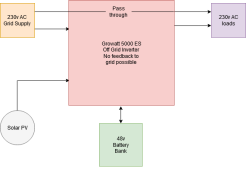
You have described this very well. This is how I perceive the SPF Growatt 5000 ES to work :
Being marketed as an off-grid inverter i.e. cannot feed power back into the grid , it should rather be called a 'grid assist' or 'grid follow' inverter.
Depending on priority settings it sources power from PV and battery to supply the loads. In case of a shortfall the inverter has a 'pass through' facility by adding grid power to the output of the inverter. If , say the battery voltage drops to a certain level , the inverter will charge the battery at the same time. The problem however is that this inverter is not allowed to be connected to the grid , as yet , without an ATS , which defeats the object of the grid charging the battery and supplying the loads and as far as I know it cannot be configured as an 'online UPS' as you described above and the power company is still concerned that linesmen can be electrocuted in case of a malfunction between grid and the DC components in the build. So , it appears that the built-in safeguards to prevent accidental feedback into the grid when the grid is down are not acceptable.
Kindly correct me if my understanding of the operation of this inverter is incorrect , otherwise it is a very well built , well priced product.Inverter flow chart.drawio(1).png
 
You have described this very well. This is how I perceive the SPF Growatt 5000 ES to work :
Being marketed as an off-grid inverter i.e. cannot feed power back into the grid , it should rather be called a 'grid assist' or 'grid follow' inverter.
Depending on priority settings it sources power from PV and battery to supply the loads. In case of a shortfall the inverter has a 'pass through' facility by adding grid power to the output of the inverter. If , say the battery voltage drops to a certain level , the inverter will charge the battery at the same time. The problem however is that this inverter is not allowed to be connected to the grid , as yet , without an ATS , which defeats the object of the grid charging the battery and supplying the loads and as far as I know it cannot be configured as an 'online UPS' as you described above and the power company is still concerned that linesmen can be electrocuted in case of a malfunction between grid and the DC components in the build. So , it appears that the built-in safeguards to prevent accidental feedback into the grid when the grid is down are not acceptable.
Kindly correct me if my understanding of the operation of this inverter is incorrect , otherwise it is a very well built , well priced product.

My off-grid AIO inverter operates as a normal off-grid system powering a light daytime load (pool pump). It has a grid AC power input if I want to use the grid to charge the battery should solar PV not be supplying enough juice (rare). While that's the job it performs on a day to day basis, this uses almost no battery as this daytime gig is powered almost entirely from the off-grid solar PV array.

The battery is really there for grid outage backup.

Aside from the off-grid loads, I also have the AIO inverter AC output connected to supply my main supply panel via a transfer switch. In the main panel I have my circuits divided into two groups - those circuits which can be supplied power via the off-grid system/transfer switch, and those which are grid-only supply and not wired via the transfer switch. Included in the latter is the grid AC input for the off-grid AIO inverter.

What this means is that when the transfer switch is set to the off-grid supply position, then the AIO is supplying the backed up circuits with power. I then have a choice on which input (i.e. solar, battery, grid) supplies the output.

If I have the off-grid AIO inverter operating in UPS mode then if the grid is up and supplying power the AIO inverter passes that grid power through to the backed up circuits via the transfer switch - so all those circuits operate as normal using grid supply. But if the grid goes down, then the AIO inverter instantly (10ms) cuts over to supply power to the backed up circuits using solar and battery.

Once grid power returns then the AIO returns to passing through the grid power and can recharge the battery if required.

Meanwhile, the non backed-up circuits only have power when the grid is up. These circuits include the grid tied inverter, oven, induction stove, a ducted and one other large aircon system and the dedicated circuit for the AIO inverter AC input.
Very interesting indeed and thanks for the reply. I constructed a separate DB for the off grid Growatt and transferred some of the loads from the grid DB to this one. At this stage lighting and TV / fibre router only but want to add fridge and freezer soon. The 48v 100Ah battery bank is thus only charged from PV during the day and if the battery is not optimally charged by the time the sun sets then I run out of power in the early hours of the morning. The problem is that , during the day , I re-direct the PV to heat up the 150lt hot water tank and once on temp it is directed back to charging the battery. I must admit that this set-up is totally experimental and not optimal as yet and my short term solution is to add a 48v grid powered battery charger to the mix to help out when there is no PV and battery starts depleting during the night. However , I loathe to spend extra money on a new charger whilst there is a perfectly good charger built into the Growatt which I am not allowed to connect to the grid. Hope this all makes sense and I am not re-inventing the wheel. I want to run my system legally without having to jump through lots of hoops and red tape required by the power company. I have no intention of ever feeding power back into the grid.
 
However , I loathe to spend extra money on a new charger whilst there is a perfectly good charger built into the Growatt which I am not allowed to connect to the grid.

SPF Growatt 5000 ES
Surely just connecting a load to the grid is perfectly fine?

As far as I can tell this unit does not even have the capability to back feed the grid in the sense a grid-tied inverter would. It has an AC input which can be a grid power supply or other suitable AC supply such as an inverter generator. This AC input connection does not back feed the grid. It presents as a load only.

It's the AC output side which will be up to you to ensure is not connected to the grid.

If it is only supplying a dedicated off-grid distribution board, then you have zero concerns with any back feeding of the grid being possible.

In my case my AIO inverter also supplies my home's circuits but via a transfer switch and it is the transfer switch which ensures the grid supply and the AIO inverter supply are never ever connected. It's a 3-position "break before make" switch.

Like the Growatt, my AIO inverter is an off-grid only unit, with an AC input and an AC output. The difference (apart from capacity/quality, mine is a cheap 48V/4kW Voltronic clone) is mine requires a battery to operate. I think that Growatt model can operate without a battery.

In my case the 230V AC input is normally a grid supply and I have the AIO input connected to a 20A plug which is plugged into a 20A grid supply power outlet. I did this rather than hardwire the grid to the AC input so I can choose to unplug from the grid outlet and instead connect my Yamaha inverter generator into the AIO to charge batteries if needed (e.g. if we have a very long grid outage with poor solar conditions).

I constructed a separate DB for the off grid Growatt and transferred some of the loads from the grid DB to this one.
Same. My off-grid AIO inverter feeds a small AC distribution panel with a common current protection breaker and two output circuit breakers - one RCBO for the off-grid power outlet (which the pool pump uses) and regular current limiting circuit breaker connected to the 20A power inlet which in turn supplies the home's main panel transfer switch. The main panel already is chock full of RCBOs. The 20A power inlet for the transfer switch and the 20A socket connected to the AIO AC input are the same type of socket so I can connect the generator to the AIO inverter or just directly feed the house if needed. I like the multiple redundancy.

The 48v 100Ah battery bank is thus only charged from PV during the day and if the battery is not optimally charged by the time the sun sets then I run out of power in the early hours of the morning. The problem is that , during the day , I re-direct the PV to heat up the 150lt hot water tank and once on temp it is directed back to charging the battery.
Yeah hot water sucks a lot of energy. It's a really good use of excess solar PV but does need a bit of load management when supply is limited and you want to prioritise supply to other loads.

Another option is a heat pump HW system which will draw way less power to heat water than a regular resistive element tank. If ambient air temp is no super sub freezing cold then you can expect your HW energy draw to be no more than 1/3rd to 1/4 of what a resistive element HW tank would use. Whether it's a suitable option will depend on your climate (and budget - as they are somewhat more expensive).

Our hot water will remain grid connected and is currently on a dedicated off-peak circuit controlled by the energy distributor but I am considering changing that to a regular anytime supply circuit and using a smart diverter so my excess grid-tied solar PV can power it instead. This would not be much of a money saver as the off-grid tariff is pretty good but it would reduce carbon emissions (our night time grid is coal/carbon intensive) and importantly it will help to lower our daytime grid voltages which are high enough to regularly cause my grid-tied inverter to throttle output and occasionally shut down if it exceeds 258V for too long. Adding load really helps keep our supply voltages down.

I must admit that this set-up is totally experimental and not optimal as yet
As is mine. It was a lockdown project. I have a thread where I describe it and what I've since done:

At this stage lighting and TV / fibre router only but want to add fridge and freezer soon.
I've only moved my pool pump to off-grid supply (and a few small sundry items like pool robot cleaner, a power tool charger), the rest of the household I am not as yet going to operate via the off grid. I would except:
- my 48V 18.2kWh battery bank is sealed lead acid (second hand data centre backup units) and so it's actually well suited to doing very little but being there when needed. I would need to add some LiFePO4 to that for regular cycling duties.
- because the main panel backup circuits also supply two other buildings (a second dwelling and my mancave) via sub-circuit boards there are a couple of high power circuits (oven/stove in the dwelling and a large aircon unit) in those other buildings which are too much for my AIO to manage. Being sub-boards I can't bypass individual circuits so easily.
 
As far as I can tell this unit does not even have the capability to back feed the grid in the sense a grid-tied inverter would. It has an AC input which can be a grid power supply or other suitable AC supply such as an inverter generator. This AC input connection does not back feed the grid. It presents as a load only.

Does it convert grid AC to DC, to power its inverter?
Or, does it pass AC through a relay to output, and synchronize its inverter to grid so it provides power to load as well?
 
Does it convert grid AC to DC, to power its inverter?
Or, does it pass AC through a relay to output, and synchronize its inverter to grid so it provides power to load as well?
That I don't know. Better to ask an electrical engineer familiar with the circuit diagram of this inverter model.

In SUB mode it can blend inverter and grid sources together to power loads, so clearly they have to be synchronised. So if I had to guess it would be #2.

From the manual:
SUB priority
Solar energy provides power to the loads as first priority.
If solar energy is not sufficient to power all connected loads, solar and utility will power loads at the same time.
Battery provides power to the loads only when solar energy is not sufficient and there is no utility.

My AIO inverter doesn't have SUB mode. It's either solar/battery powering the load or the grid powering the load, never blended.
 
In SUB mode it can blend inverter and grid sources together to power loads, so clearly they have to be synchronised. So if I had to guess it would be #2.

In that case, I think it does have the possibility of backfeeding grid, so could represent hazard to linemen.
I think something like UL-1741 active anti-islanding would be appropriate.
 
Back
Top