• Have you tried out dark mode?! Scroll to the bottom of any page to find a sun or moon icon to turn dark mode on or off!

diy solar

diy solar

DIY Lifepo4 on 39' Privilege Cat (with Boat Rewire)

manly

New Member
Joined
Jun 23, 2021
Messages
49
This thread is for logging the journey of installing a DIY lifepo4 bank on our 39' cat which I'm fitting out to be off-grip electrically. As far as builds go, this is fairly vanilla. But perhaps it will be of interest to someone and, in any extent, I can refer back to it in the future.

This post will recap what has been done so far and give an introduction to my philosophy.

First, why DIY? Why not drop-ins? Cost is definitely an issue. But more than that, even if drop-ins were handed to me (which in fact they were, Qty 10 perfectly good Battle Borns are in the boat now which I'm replacing), I still would prefer my DIY pack. Because I want to know how it works and is setup. What assumptions went into the battery builds. And I can check the cell health of each cell. Even more importantly, at the end of this project I'll be far better equipped to troubleshoot and fix a problem when/if it arises. If I'm off-grid in a remote island chain and my drop-in batteries give me trouble, I won't have the skills, knowledge, or even tools to be equipped to fix them. Additionally, I would like the batteries to have internal heaters which mine currently do not.

It is unfortunate that LiFePo4 is so finicky. The Pros in why they are advantageous, and for what I'm trying to do on 12v, pretty much essential. (i.e. run air conditioning, piston pump water maker, washing machine, hot water heater, etc.) However, the cons are increased complexity to manage (temperature, over/under voltage protection, etc). Complexity is never good on a boat. But if we must have it, at least I want to understand it as much as possible.

Ok, onwards to the details:

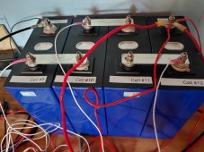
I purchased 16 cells of the supposed Grade A variety from AliExpress. From the LiitoKala&VariCore Flagship Store, to be precise. These were 280ah 3.2v cells [note: in future posts I discover they actually shipped me 240ah cells]. Cost with shipping to Florida was $1754.50. Took about 3 months to arrive (purchased 2021), but they were well packaged and I didn't see any damage. So the bank is 1,120 amp-hours. My initial capacity tests show the batteries are not pulling the full rated 280ah each. I'm going to re-test with a Renogy shunt and try to get more definitive numbers. However, if I only end up with 1,000 amp hours, that is still an adequate bank for us.

I will say that sending $1700 to China via AliExpress for batteries is heartburn inducing. And waiting 3 months for them to arrive... definitely felt like a gamble.

The BMS's I'm using are Overkill Solar. Qty (4) of the 12v as I'll be making 4, 12v batteries. Cost of these BMS's with shipping was $607.76. The upside of Overkill BMS's is they appear exceedingly robust and conservative in design. One downside is the 12v model only supports 120amps current (charge or discharge) per BMS. This would be a deal breaker if I only had 1 or 2 batteries. But with 4, that yields 480 Ah discharge capacity, which is more than enough. And charging will be under 200 amps, so no issue there.

I toyed with the idea of 24v system, and even originally bought the Overkill Solar BMS's for 24v. But in the end, I wanted to keep things as simple as possible, so sold those and bought the 12v ones.
 
Last edited:
Battery Case And Location:

The case has been a topic of much thought. In the end, I'm going with the plastic battery boxes from AliExpress. Their outside dimensions are 345x245x190mm. Still waiting for those to arrive as I ordered them recently. Cost for 4 with shipping was $250.32. These have come down in price, I'm assuming as DIY has become less popular now that prices have really come down on out-of-the-box solutions.

I've gone back and forth on cell compression. I would prefer to wrap the 4 cells together with Kapton tape and be done with it. This is controversial, but I noticed even SOK batteries, which are regarded well by Will, are not compressed. So though my batteries may not last as long, the setup is simpler and the footprint can be smaller. However, being subjected to loads while sailing, I understand it is important for the installation to be solid.

Planning for each battery to have an internal heater. Though I'll mainly be in Southern latitudes the next few years, I'm hoping this battery bank to last 10+ years, and in that timeframe I very well may cruise North.

The batteries will be mounted in the starboard engine room. That is where the current batteries are. There is lots of chatter about how heat is bad for these batteries and the engine room is not an ideal place for LiFePO4 batteries. That is certainly true, but my cat is a sailboat and besides that, most the time it is at anchor. So time the engines are being run is very little in the grand scheme of things. And when the engines are running the blower will be on to circulate air through that space. The bigger issue in my mind is the additional vibration in the engine room. But that is the most logical place for the electrics to go, so that's where they're going.

For reference, here is an informative article on marine LiFePO4 installations: https://nordkyndesign.com/assembling-a-lithium-iron-phosphate-marine-house-bank/
 
Last edited:
Battery Posts & Tools:

Some nitty gritty. For the battery posts, here is hardware used:

Hardware for Battery PostsCost / EaQtyTotalLink
M6 Lock Washers (pack of 100)$11.141$11.14https://www.mcmaster.com/97079A103/
M6 Set Screws (pack of 10, 20mm long) 92029A260$4.264$17.04https://www.mcmaster.com/92029A260/
M6 Nuts (pack of 50)$9.391$9.39https://www.mcmaster.com/94150A345/
M6 Washers (pack of 100)$6.001$6.00https://www.mcmaster.com/98690A113/
T-Handle for 3mm 6954A22$4.701$4.70https://www.mcmaster.com/6954A22/
Loctite 263$15.331$15.33https://www.mcmaster.com/91458A610/

I went stainless steel. Some on here recommend copper screws, and that may have been preferred. However, I've also seen other use stainless without any ill effects. I've loctighted in the studs on all 16 cells without issue.

There were some tools invested in for the project:


I already had a number of electrical tools (wire strippers, voltmeter, soldering gun, etc) but now I'm even more prepared.
 
Last edited:
Charging sources for the LiFePO4 Bank:

Boat is currently equipped with 1920 watts of solar that charge the house bank via 4 separate Victron charge controllers. These are already installed. Additionally, I'm adding a 30 amp DC-DC Orion from the starter battery to the LiFePo4 house bank that will run when the alternators are running (boat is equipped with 2 70 amp stock alternators on 30hp engines). Alternators will go to the starter battery only. I'm NOT planning to have a combiner switch for starter and house banks. There is one now, but I'm taking it out. I want to keep the banks totally separate for simplicity (except the Orion charger). If for some reason my starter battery dies, I'll rig up jumper cables from the house battery. Also, for charging sources, the 30 amp charger from the alternators is kind of a joke, since with such a large bank it would take over 24 hours to charge by alternator alone. However, as an emergency backup, I like having this option. And the 30 amps shouldn't tax the alternators much, even if I'm only running one engine to conserve fuel.

The last charging source I'm thinking of adding in the future is a wind turbine. This one: https://store.marinebeam.com/marinekinetix-mk4-marine-wind-generator/

Of note, I'm not planning to have a diesel or gasoline generator on board. A built in generator takes valuable room (our Cat is only 39' so space is precious). A gasoline generator, such as the Honda 2000, may be a valuable backup piece of kit (and I may succumb), but as of now I don't want it. It must be stored, maintained, I would need to carry additional gas (already carrying too much gas for the dinghy), and there is the increased danger of carbon monoxide poisioning. If the solar is not cutting it, instead of throwing $ at a Honda generator, I plan to throw $ at a wind generator instead.

Finally, on charging, it goes without saying that I am not factoring in marina shore power. Though I do have a shore power hookup that goes through Victron Multiplus 3000, I'm intending to keep this boat off-grid indefinitely.
 
Last edited:
Current Project Status as of 11/25/22:

I've had the battery build project on the back burner for over a year. I'm finally getting back to it. So far I've top balanced 3 of the batteries, and am working on the 4th.

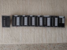
Concurrently with this project, I'm also re-wiring the Cat and replacing breaker panels. I'm using Paneltronics breakers: 6 DC panels with 8 breakers each, and one AC panel with 5 breakers. Additionally, 3 Sea-Dog switch panels used in various spaces. And a plethora of fuse boxes and terminal strips located around the boat. I may post some of that on this thread as well, if anyone is interested.

The entire project sounds complicated, but once it is all done the layout will be quite straightforward. And I'm documenting everything, so fairly easy to troubleshoot in the future. I want the electrical system to be as simple and robust as possible, with redundancy and, as much as possible, running in a closed system on renewable energy sources.
 
Battery Specs:

My cells are supposedly Lishen. And, for future reference, here are the specs from the AliExpress listing:

Product name:lithium iron phosphate cell
Shell Material:Aluminum
Nominal capacity:280Ah
Minimum capacity:280Ah
Internal impedance:0.1 ~ 0.3mΩ
Nominal voltage:3.2V
Discharge end voltage:2.5 v
Recommend constant current:280a (1c)
Recommend constant current:140a (0.5c)
Charging voltage:3.65 v
Maximum continuous discharge current:280a (1c)
Life cycle (80% dod):4000 cycles
Charging temperature:-5 60 60 ° c
Discharge temperature:-30 60 60 ° c
Dimensions (l*w*h):205*174*72mm
 
You can look up your cells here if you’re curious :

 
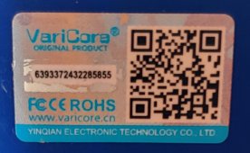
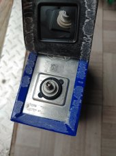
@JoeHam My batteries don't appear to have legit barcodes. There is a barcode but it just goes to varicore.com. See attached.

By the barcode there is also a "scratch-off" area revealing a long string of numbers. I don't know how to interpret these numbers, and when I plugged it into your link above it didn't recognize the format.

See attached.

So I guess this means I have Grade B cells?
 

Attachments

  • 20221125_144116_HDR.jpg
    20221125_144116_HDR.jpg
    381.8 KB · Views: 16
  • 20221126_104517_HDR.jpg
    20221126_104517_HDR.jpg
    501 KB · Views: 16
  • 20221126_104524.jpg
    20221126_104524.jpg
    517 KB · Views: 16
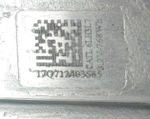
I just peeled up under the black top part and saw what looks like the original barcodes.

However, the numbers still don't work for me on that website link.

Here is what I read:

17Q712A0356565
CATL 6IH3L7
3.2V - 768 Wh

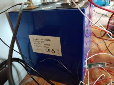
The 768 Watt-hour solves a mystery though. I've been pulling slightly over 240 amp-hours on capacity tests (like 242). It says on the side they are 280amp-hours, and they were advertised as such, but in fact they are 240 amp-hour batteries.

I just reached out to the vendor to see what they say.

With these lifepo4 builds, you don't know what you don't know.
 

Attachments

  • Barcode Zoomed in.jpg
    Barcode Zoomed in.jpg
    328.5 KB · Views: 5
  • 20221126_110925.jpg
    20221126_110925.jpg
    344.8 KB · Views: 6
*** Battery Boxes ***

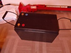
Received 2 out of 4 battery boxes. The other 2 should arrive soon. Pretty excited to finally see these in person. I've thought about a lot of DIY options for boxes, but these seemed like a good solution. They are sturdier than I was expecting. A year ago when I first received my cells these were going for about $150/ea. I bought these for $62.50, so the price has really come down. Still, it's nerve racking buying anything AliExpress. For one thing the ads are confusing about which size will or will not fit. These are the 345x245x190mm size and fit my 240 ah fine. Also they work with 280 ah.

*** Battery Capacity Testing after 1 year ***

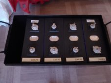
It's been over a year since I received my 16 cells and capacity tested them in 4 batteries, 12v each. The 4th battery I never got around to even touching.

Most of the last year they were on my boat in the forward locker which got very hot in the Florida sun through this past summer. Not an ideal place for storage.

Also, these were left mostly full. Not 100%, but 70% or so.

I feared there may be significant degradation if I re-capacity tested them now. So I went ahead and re-tested all 4 batteries. And... I was pleasantly surprised they still seem in great shape. 3 of the 4 pulled 240 ah (and I stopped the test when they hit capacity). The only one that didn't was Battery #2 that I tested last and, out of curiosity, didn't do a top balance first (the other 3 I top-balanced and then tested). However, battery #2 had been top balanced a year ago. It only pulled 238 ah. I'm recharging it now and will top balance it again and re-capacity test it to see if it pulls the 240.

Capacity ResultEnd VFinal Voltages
Battery #1Completed Top Balance & Capacity Test 12/3/22240 ah11.04(#1: 2.801, #2: 2.838, #3: 2.703, #4: 2.704) Delta .135v
Battery #2Completed Capacity Test 12/6/22238.2 ah10.86(#1: 2.803, #2: 2.573, #3: 2.662, #4: 2.830) Delta .257
Battery #3Completed Top Balance & Capacity Test 11/27/22240 ah10.95(#1: 2.842, #2: 2.793, #3: 2.703, #4: 2.618) Delta .224v
Battery #4Completed Top Balance & Capacity Test 11/30/22240 ah11(#1: 2.874, #2: 2.829, #3: 2.801, #4: 2.895) Delta .094v

Looking forward to getting these put together and finally having actual batteries to work with.
 

Attachments

  • 20221206_174738_HDR.jpg
    20221206_174738_HDR.jpg
    283.2 KB · Views: 13
  • 20221206_174746.jpg
    20221206_174746.jpg
    251.8 KB · Views: 13
Last edited:
Completed a top balance on Battery #3 and then immediately started another battery capacity test. The result was 239.0 ah. Still 1ah shy of rated capacity. But that's still 99.5% of rated capacity, so not bad after over a year of calendar aging in a hot compartment.

Final results:

Capacity ResultEnd VFinal Voltages
Battery #1Completed Top Balance & Capacity Test 12/3/22240 ah11.04(#1: 2.801, #2: 2.838, #3: 2.703, #4: 2.704) Delta .135v
Battery #2Completed Top Balance & Capacity Test 12/8/22239 ah11.2(#1: 2.853, #2: 2.720, #3: 2.740, #4: 2.889) Delta .169
Battery #3Completed Top Balance & Capacity Test 11/27/22240 ah10.95(#1: 2.842, #2: 2.793, #3: 2.703, #4: 2.618) Delta .224v
Battery #4Completed Top Balance & Capacity Test 11/30/22240 ah11(#1: 2.874, #2: 2.829, #3: 2.801, #4: 2.895) Delta .094v
 

Attachments

  • 20221208_204323.jpg
    20221208_204323.jpg
    80.5 KB · Views: 11
I've been working on getting the circuit breakers together for the boat. One step closer.

Also, the other two battery boxes came in from China, so now I have all four. They were all damage free and arrived in 2 weeks. The seller was Dongguan Teswatts Batteries Store from AliExpress. Came with Qty (8) bolts but I would like 16 so I can bolt from the bottom and the top. I need to figure out the threads.

I've been working on making a mounting plate system in CAD that will fit in the spare area of the box and hold the BMS and also "squeeze" the pack enough to keep it in place and not shift, even if turned upside down.
 

Attachments

  • 20221210_150134~2.jpg
    20221210_150134~2.jpg
    508.4 KB · Views: 37
Last edited:
Here is the link to the battery case. This was the best deal I could find on AliExress. Some looked cheaper but the shipping was higher. I bought 4, shipped to my door for $250.32. 2 weeks delivery. Looks like these fit a number of cases in the 200-300 ah range. I bought the ones with the M8 screws. But they only come with 2 per box, and you need 4 per box. 2 to screw in underneath and 2 to screw in on top. These are about 12mm long bolts (apx 0.5") and there are enough threads to screw in from top and bottom. So about 1" of threads.

 
Battery #1Completed Top Balance & Capacity Test 12/3/22240 ah11.04(#1: 2.801, #2: 2.838, #3: 2.703, #4: 2.704) Delta .135v
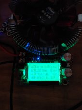
I have a question about using that tester. I have the same one from Amazon.
When testing a single cell, starting at 3.4V and discharging at 20A, the tester immediately shows voltage drop to ~3.1V (DMM still measures ~3.4V).
So tester displayed volts when discharging about .3V low. I set my test stop voltage to be 2.7V so my tests actually stop when cell voltage is about 3.0-3.1V.

Are you seeing voltage differences/ issues like this?

I am getting about 260Ah out of 280Ah cells and that seems about right discharging to 3.1V. But some cells vary a lot, 3.05V to 3.2V at the end so thinking tests are inconsistent and invalid.
 
Thank you very much for sharing all this info and detales. I'm also planning to do big remake of my electricity on Sun Odyssey 49, with also 16 cells of EVE LF280K and its great to be able to learn from your experiance. Keep posting .
 
@MisterSandals yes, I see a smalle rvoltage at the chinese capacity tester compared to the battery. I assume that is because of the resistance in the wire.

Attached is a picture with voltages circled in blue. You can see the capacity tester measuring 12.8 volts while the Renogy battery monitor mesaures 13.0 volts.

I haven't tested cells individual, only 4 in series. As an aside, I've been running the tester about 10 amps. When I go higher it gets too hot for my comfort.

Besides the voltage issue, the amps is really what gets me. Nothing seems to match. See the attached picture where I have the amps circled in red. The chinese tester reads 10.3 amps discharge, the Renogy battery monitor reading 10.2 amps, and a Klein meter between the shunt and the capacity tester reads 9.99 amps. I'm not a "sparky," so don't understand why the disparity.

But regardless, I've found the chinese capacity tester and the Renogy battery monitor agree within 1-2 amp-hours over the 240 amp-hour test of my batteries. Renogy monitor usually shows 1-2 amps less capacity than the chinese capacity tester. I take this as confirmation that my batteries are pulling close to their rated capacity and the system works well enough for my needs.

My goal is to put this battery into service and get a 10 year life from it. Not planning to sell the boat in the next 10 years.

@Dr.Maro Glad this is helpful to you. The Sun Odyssey is a nice boat, also French like mine. Have you purchased cells yet?
 

Attachments

  • 20221126_080942_2.jpg
    20221126_080942_2.jpg
    245 KB · Views: 18
For last 2 weeks going around different cell suppliers and comparing all, so as the regulated battery chargers and meaters etc
So Believe to start all in Januray / Feb.
 
Am resuming the project... the distribution part of the project is starting to come along. Just laying out how all the wiring on the boat is going to go took quite a bit of thought / time.

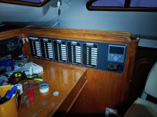
I installed 5 circuit panels at the nav station. These are all DC 8-position panels made by Paneltronics. You can buy them a number of places, I got most of mine from Defender.com. They are $120 each. I have these 5 (pictured below mounted at the nav station) as well as 3 more located elsewhere. Only 1 of the 8 is an AC panel, the rest are DC. These panels have negative busses on the back, which for me was a plus as I'm running all the wiring directly to the panel. I know it's not recommended to do that, but to instead go to terminal strips that in turn run to the panel. However, I have excellent access to the back of my panels, so for simplicity I'm just going straight to the panels.

These Paneltronics are about half the price of the equivalent product by Blue Sea Systems. I'm impressed with the build quality.

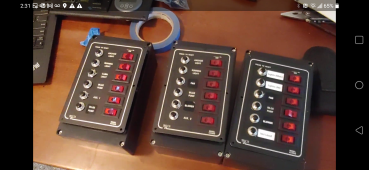
Besides all those, I'm also distributing loads with 3 Sea Dog panels located in various rooms. Attached is a picture of those as well. I mounted them in project boxes (10.4" x 7.2" x 3.7", $20 at Amazon here).

Also using a number of Blue Seas Systems fuse blocks as well, as well as a host of terminal strips.

This boat has quite a few systems.
 

Attachments

  • Sea Dogs Breakers.png
    Sea Dogs Breakers.png
    1.4 MB · Views: 31
  • Panels installed at nav station.jpg
    Panels installed at nav station.jpg
    604.5 KB · Views: 30
  • Behind Circuit Breakers.png
    Behind Circuit Breakers.png
    2.4 MB · Views: 18
Last edited:
With regard to your installation in the engine room. What we know about lifepo4 and heat. 25degC is perfect for lithium. 35degC constant ambient temperature will half the life. 45degC will half it again. We cruise the Caribbean in winter and the batteries sit at ambient most of the time plus a bit if we are charging. So the lowest we see at the moment with the battery box lid permanently off whilst at anchor is 27degC. This can creep up to 29degC. By comparison, our engine room gets to 40degC with the engine running and the ventilation on. This is air temperature. Radiant temperature off the engine block that sits at 80degC when running with raise the temperature of anything in there further. Although you won't see the high temperatures on the batteries permanently due to the engine heat, it will be high temperature. This will have an effect on battery life.
The impact of high temperature on lifepo4 is not talked about much but its real. I am working on a liquid cooled lifepo4 commercial project at the moment. For tropical locations we expect 25% increase in battery life and the ability to charge and discharge at high rates with no impact on battery life.
 
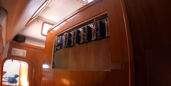
I've slowly been wiring up various circuits. It's really a slog and much more time-consuming than initially anticipated. I'm about 60-70% complete with the wiring.

Back of Power Wall.jpg

*** Main Breaker Panels ***

Since my last post I added in the battery monitor and 3 switches. Also wired in the Color Control. Those 3 switches are all salon lights.

Breakers.jpg


*** Breaker "Splitter" Panel ***

How to layout the breakers was a topic of some thought. There are many ways to organize the power flow throughout the boat. In the end, what I came up with is 2/0 Cables feed into 7 breakers which in turn feed 7 panels.

In the picture below, the 2/0 input cables from the batteries are coming up from the bottom. They first go through a 150 amp breaker, then various circuit breakers that feed various panels.


Splitter Breakers.jpg

The empty spot in the wooden panel above is where the 110 AC breaker panel will go.

For reference, here is what it looked like before I started:

Wiring Before.png

*** Layout for all the breakers ***

Main Panel 1 - Lights, Auto Bilge, Misc (40 Amp Breaker)Breaker SizeUnit
1Automatic Bilges30amps
2NMEA 20005amps
3Anchor Light / Tri-Color / SOS2.5amps
4Fwd Nav Lights2.5amps
5Steaming Light2.5amps
6Deck Light2.5amps
7Stern Light2.5amps
8Computer5amps
Main Panel 2 - Manual Bilges (50 Amp Breaker)
9Bilge, Port Forward Locker5amps
10Bilge, Port Midships (Main)5amps
11Bilge, Port Engine5amps
12Bilge, Port Head5amps
13Bilge, Starboard, Forward Locker5amps
14Bilge, Starboard Midships (Main)5amps
15Bilge, Starboard Engine5amps
16Bilge, Starboard Head5amps
Main Panel 3 - Accessories (70 Amp Breaker)
17Victron Color Control5amps
18Nav Station USB10amps
19Stereo10amps
20Refrigerator, Port15amps
21Refrigerator, Starboard15amps
22Fresh Water Pump15amps
23Saltwater Pump20amps
24Propane Solenoid & Sniffer5amps
Main Panel 4 - Operational (50 amps)
25VHF10amps
26AIS / Splitter / GPS5amps
27Chart Plotter10amps
28Helm Station10amps
29Auto-Pilot30amps
30Windlass5amps
31Radar10amps
32Spare5amps
Main Panel 5 - Compartments (70 Amp Breaker)
33Staterooms, Forward5amps
34Stateroom, Aft Port10amps
35Salon, Port10amps
36Salon, Starboard10amps
37Galley5amps
38Engine Room, Port, Sub Panel20amps
39Engine Room, Starboard, Sub Panel20amps
40Cockpit10amps
*** Sub Panel in Starboard Head which has Toilet only *** (100 Amp Breaker)
41ElectroSan60amps
42Toilet30amps
4312V Charging Hallway10amps
44Aft Stbd Cabin10amps
45Starboard Hallway2.5amps
46Macerator20amps
47Head Bilge5amps
48Head Lights2.5amps
*** Sub Panel in Fwd Starboard Locker (i.e. water room) ***
49Light & Fan, Stbd Fwd (2 amp)3amps
50Light & Fan, Center Fwd (2 amp)3amps
51Light & Fan, Port Fwd (2 amp)4amps
52WM Feed Pump (5 amp)6amps
53WM High Pressure Pump Relay (1 amp)4amps
54Bilge Pump6amps
*** Sub Panel in Port Engine Compartment ***
55Light (Main)10amps
56Lighs (Aft)3amps
57Fan3amps
58Blower6amps
59Bilge6amps
60Spare8amps
*** Sub Panel in Starboard Engine Compartment ***
61Light (Main)10amps
62Lighs (Aft)3amps
63Fan3amps
64Blower6amps
65Bilge6amps
66Spare8amps


*** Batteries in the Engine Room ***

@TimE, you're correct that the life of the batteries will be shortened some by the heat of the engines. However, I don't anticipate running the engines that much in comparison to the life of the batteries. Perhaps a few hours per week. So hoping the impact will be negligible.

*** Fuse Boxes ***

There will also be a number of fuse boxes throughout the boat in addition to all these breakers. It's enjoyable putting it all together, but it does take time. One nice thing is actually seeing things start working around the boat as I get each circuit hooked up.

*** Victron Color Control ***

The Victron Color Control came with the boat so I'm using it. However, there are only 2 USB ports and 2 VE.Direct ports. I'm using a powered USB splitter to get more ports. Here's how I have things laid out:

VE.Direct #1 - Solar Charge Controller 1
VE.Direct #2 - Solar Charge Controller 2
USB Port #1 - Batter Monitor (VE.Direct to USB Cable)
USB Port #2 - Powered USB Splitter

USB Splitter Port #1 - Solar Charge Controller 3
USB Splitter Port #2 - Solar Charge Controller 4
USB Splitter Port #3 - Wifi Dongle

The charge controllers are about 30' of wiring distance from the Color Control so I've had to daisy link VE.Direct lines and also the USB cables. Fortunately it all works.

The new Cerbo VX has more ports, which would be nice.
 

Attachments

  • Back of Breaker Panels.jpg
    Back of Breaker Panels.jpg
    456.9 KB · Views: 17
Last edited:
And the AC main panel is now wired.

AC Panel.jpg

Front of AC Panel.jpg

And, for reference, here is the same area before:

AC Wiring Before.png
 
Last edited:
For record keeping, I've made a spreadsheet that shows which wires run through every transit (PVC pipes) on the boat. This should be handy in the future for any troubleshooting.

I took a stock overview diagram of our boat and labeled in the transit locations:

Transits.png


Here is a representative sample from the spreadsheet, just to give an idea of how tedious all this record keeping is.

Transit F - K (Starboard engine room to distribution panel / Inboard PVC transit)Description of WireEnd A End B
These 7 are bundled and go up to the Victron Color Control:
Solar Charge ControllerBlack VE.Direct Solar Charge Controller WireSolar Panel Charge ControllersColor Control
Solar Charge ControllerBlack USB Wire (Converts to VE.Direct in port engine room)Solar Panel Charge ControllersColor Control
Battery shunt wireSmall grey wire, 24 awgShunt at batteriesBattery Monitor at Nav Station
Inverter Control Cat5 WireBlue Cat5Victron InverterInverter Control Panel at Nav Station
NMEA 2000 BackboneBlack WireStarts in the starboard area by fridge compressorEnds in port enigne room.
These 10 are bundled and go the Nav station just fwd of the bundle above.
Bilge Wire for Starboard EngineLarge Dark Grey, Round, 14 AWG w/3 conductors (Black, Red, Brown)Bilge Distribution PanelStarboard Engine Bilge
Bilge Wire for Port EngineLarge Dark Grey, Round, 14 AWG w/3 conductors (Black, Red, Brown)Bilge Distribution PanelPort Engine Bilge
Auto-Pilot10awg Ancor 2 strandDistribution Panel, OperationalPort Engine Room
Chart Plotter12awg, 2 strandDistribution Panel, OperationalPort Engine Room
Aft Port Cabin12awg, 2 strandDistribution Panel, CompartmentsPort Aft Cabin Closet (through Port Engine Room)
Propane Solenoid & Sniffer14awg, 2 strandDistribution panel, AccessoriesPort Engine Room (splits to 2 wires for sniffer & solenoid)
Helm Station14awg, 2 strandDistribution Panel, OperationalPort Engine Room - splits to fuse box for powering various helm station items
NMEA 2000 (inject DC power in port enigne room)14awg, 2 strandDistribution Panel, OperationalPort Engine Room
Cockpit14awg, 2 strandDistribution Panel, CompartmentsCockpit (through starboard engine room) has a terminal strip that splits to dinghy light & cockpit
Stern Light16awg 2 strandDistribution Panel, LightsAttached to aft end of solar. passes through Starboard Engine Room


Never fear, I'll get to the Lifepo4 installation at some point!
 
Last edited:

diy solar

diy solar
Back
Top