diy solar

diy solar

DIY, Low Cost Generator From Vehicle Alternator (Alternating Generator)

JeepHammer

Solar Wizard
Joined
Nov 15, 2019
Messages
1,149
Having rebuilt Alternators for a living,
I would like to pass along something that fits the needs of DIY types quite well in my experience.

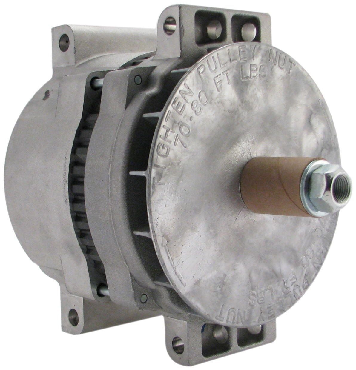
This is a Leece-Neville alternator...
And it has some interesting features that DIY types will find interesting, and they are in salvage yards everywhere being used on large vehicles from the 70s to present.

LN-2824LC-2.jpg


1. Being available in 6, 8, 12, 18, 24, 36, 48 and 56 volts, 60 to 300 Amps.
This makes them comparable with about any battery string voltage or amperage.
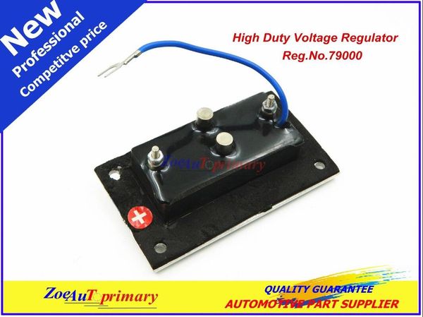
2. Adjustable voltage regulator,
3. Isolated Negative, the alternator frame/mounts aren't 'Grounded', so reverse polarity is easy,
4. Easy to add a second rectifier externally, outside the case in the back, when you want to heavy load the generator,
5. External AC taps, direct access to AC production (high frequancy AC welders sould take note, speciality welding is possible),
6. External voltage regulator, it's simple to take control of the rotor or switch back to regulator.
7. There is enough room in the case to rewind for higher voltages or amperages.
8. Available in both common or 'Flat' mount versions.

Flat mount version,

ec6a0be9-d789-478d-a67c-bfd8332cd632_1.9e1dd4add6112e8f0737fed6e54122a0.jpeg
 
Last edited:
The top two terminals,
Left, 'IGN' or Ignition terminal is the Excited, used to get the unit charging.
Right, the Tachometer connection, used on diesel engines that don't have distributor ignitions.

41sfm8%2B-mvL._SY355_.jpg


The two large terminals, far left & right are Positive & Negative output to battery or load.
The three smaller terminals are the Stator AC taps, direct access to the Alternating Current before the Rectifier.

The Regulator is held in the top by 4 screws,
Has two terminals on the bottom that control the Rotor (via brushes) and applying controlled voltage here allows you to control output voltage.
(Assuming rotor speed is constant)

This allows you to easily control the output, AC or DC when welding or using the unit for other than regulated charging.

rBVaI1jCiW6AO90SAAE4sp95np4398.jpg


A voltage regulator with adjustable output voltage allows you to fine tune the output while the regulator controls things. These came standard on many models so they are available factory stock.

The RED button on this voltage regulator has the voltage adjustment control under it.

2800J1.jpg
 
Last edited:
Since Negative is isolated, this is ideal for welding since reverse polarity is commonly used for welding.
(Positive work piece, Negative electrode)

The Rectifiers can be doubled, an extra set added on the back of the case so load is spread out among more diodes, and there is more heat sink surface area.
This is a version with doubled Rectifiers/Heat Sinks, a little bit different version than above, but the finned things sticking out the back are added Rectifiers.

1159e7b20754ab3a295b79.jpg
 
Some Alternator Basics And Starting With The Most Common & Cheapest Alternator Out There,
But The Basics Apply To Every Alternator On The Market.

The GM Small 'SI' Series Alternators Are Everywhere & Cheap.

---------

Schematics And Real World So You Can Identify Parts & What They Do.
The round circle with the 'Y' in the middle is the schematic for the STATOR, the loops of stationary wire inside a the alternator case.
This shows connections from Stator (AC production) to Rectifier Diodes.
Diodes 'Rectify' the AC into DC (Direct Current).

Direct Current is flat and steady.

FLATDC.JPG

I encourage EVERYONE that wants to understand how to generate a USABLE electric current,
Study the Electro-Magnetic Link.
When a magnetic field (Magnetic 'Arc' Lines) pass through and electrical conductor (wires),
The magnetic field 'Induces' (Induction) an electrical current.

A SPINNING in a coil of wire would produce first positive, then negative electrical current, as first the 'North Pole' of the magnet passed tough the winding, then the 'South Pole' passed through the winding, over and over again...

SINGLEAC.JPG

A Diode is a one way 'Gate Valve' that's polarity sensitive.
Diodes in pairs will separate the 'Positive' pulses, and the 'Negative' pulses into a useable form of Direct Current (DC).

singlerec.jpg

While the magnetic field spins (North/South), and alternator has 3 sets of windings, spaced 120° apart, so you get 3 power output from one flip of the moving magnetic field.

RIPPLE01.JPG

A Capacitor is used to smooth out the 'Ripple Effect', and the alternator puts out a fairly steady, useable form of DC.

In Electrical Schematic, this is what the Stator windings (left) and the Diode Rectifier (right) look like.
What the Stator Windings actually look like, see below, the back half of an alternator case, look for copper wires in a metal frame just inside the case housing.

BBS1.gif

This is a Rectifier Bridge & Heat Sink in a GM SI alternator.
An actual picture, an explanation of what you are seeing, and a diagram of AC (Red & Black Connections) going into the Rectifier, and the Positive/Negative DC connections after AC goes through Diodes.
The Rectifier is designed to handle the full current production from the Stator.

alt17.gif

This shows how the Diode Trio is attached, what it looks like in one version of these little alternators.
The Diode Trio is a direct sample of Stator Output supplied to the Voltage Regulator, it's removed when you want to take control of production, taking the voltage regulator out of the system.
Some alternators won't have an internal regulator, some have external regulators, either in the wiring harness someplace, or on much newer models, the vehicle computer takes over the voltage regulator duties.

With this version the Capacitor is attached to the right side.

22SIDiodeTrio1.gif

This is the back case of another version of GM SI alternator, notice the diode trio and capacitor are not attached.
Both are there, but this version uses the canister type capacitor.
The mounting screw is the negative contact for the Capacitor, GM SI alternator are case Negative Polarity commonly, so keep that in mind when experimenting...

alt08.gif

This is another version of the GM SI alternator back case.
Even though this is the ugliest, most dirty example I could find, it still produced 850 Watts like a champ!
There are versions of this little, cheap, basic alternator will crank out 1,620 Watts from about any drive source.

alt07.gif

'Grounding Out' the 'Test Tab' to the case will force the alternator to go 'Full Field' and output at maximum.
The screw just above the 'Test Tab' has an insulator collar around it, remove that collar and you can weld off this little guy! (Full Field - Full Time)

By adding as second Rectifier (outside the case back), and jumping AC taps to that second Rectifier, the little unit will last MUCH longer at full power output.
Several alternator types have cases drilled straight through for rectifier mount screws, longer screws or bolts/nuts make for easy mounting of that second Rectifier.
 
Last edited:
Just parking some diagrams here for use in a while when I get time and find things

Top in this image is the standard vehicle alternator in electrical schematic, along with the Rectifier Diodes that convert to DC current, you CAN connect to the AC directly from the Stator, and use that AC for certain things, like brush type motors (Most Hand Tools).

The two wire plug drills, saws, etc. (The less expensive ones with plastic cases) are almost all brush type motors and will run off AC from the average alternator Stator.
This is STRICTLY a 'Hot/Neutral' wiring system, there is no 'Ground', and metal case tools that need a 'Ground' (3 wire plug) should not be used in this application.
I won't use a 3 wire ('Grounded') outlet to prevent use of devices that rely on a 'Ground' to be safe.


ACtapsYwound01.gif

DO NOT plug anything with a transformer or sensitive electronics into these outlets!
The FREQUENCY will be MUCH higher than the standard 50-60 mHz of grid power and you WILL kill your electronics!
Brush type motors could care less, but it will overheat transformers, the transformers will crank out much more current than they should, indiction motors *May* overheat, you will just have to try and see...


---------

I didn't spend much time on the Alternator Rotor...

What the Rotor does is produce a Magnetic Field that spins in the Stator.
That's about it.

It's a coil of wire that produces a magnetic field (Electro-Magnetic Link again) when an electrical current is run through that coil of wire...
The only thing unusual is the 'North' and 'South' pole designs,
Being 'Pedals' that alternate North/South really quickly creating more flips in polarity and Inducing more current in the Stator.

ROTOR01.GIF

What a rotor actually looks like, but this one is attached to the front of the alternator case by the bearing, I didn't push it out completely.

The slip rings are just Positive/Negative voltage to the winding the voltage regulator controls (in factory form),
Or you take control of the voltage to the Rotor winding to force the unit to do what you want.

ROTOR02.GIF
 
Last edited:
this if fabbed onto a old pressure washer (commonly found cheap in spring with blown pumps) or mower would be a good quick and dirty bulk charger.

if done on a engine with electric start it could even be automatic. if bank gets over 50% DOD on comes gen. ofcourse you'd want better mufflers on intake/exhaust.

The small Delco SI series are really popular with the wind generator crowd with a permanent magnet Rotor.

With a rubber shock absorbing coupler, lawnmower motors do OK with them, like the pressure washer motors,
Doesn't matter if it's a side shaft or vertical shaft engine.
A diode and side plug is all you need for a regulated 12 volt power supply.

The newer Delco CS series for computer cars give a much cleaner power supply, and work just as well.
Voltage Regulators & Rectifiers catch start up & kick-in voltage spikes and the output is much smoother & cleaner.
These are everywhere, and while a little harder to work with due to silver soldered rectifier connections instead of bolted ring terminal connections (actual silver solder takes high heat), they are still viable as generators.

For someone doing a small backup system, this is a very reasonable cost option to extend your power with what's 'Junk' parts and a little gasoline.
Your emergency rig can recharge, or even supply power for small loads.

------------

With the larger Leece-Neville unit, and batteries as a buffer, you can do sustained welding!
That's a LOT of power!

At about 4,000 Watts, controllable by line voltage, commonly 12 or 24, will pull a BIG inverter while charging the batteries it's connected to.
A big riding mower engine will power that 4,000 Watts, but use belts to drive it, this absorbs engine vibration & dampens crankshaft surge.

Since you can supply inverter directly with correct voltage AND you can supply chargers with correct input voltage directly, it's dirt simple to hook up.
You can use it to take the place of panel input,
Or you can charge common batteries directly since the unit has a volt/amp regulator built in, AND supply the inverter, it's pretty handy to have.

------------

The riding mower frame...
Has wheels, is self propelled, has a belt clutch built in that used to start/stop the blades,
Built in fuel tank, carries the weight of batteries, inverter, etc.
Turn a generator (or two) nose down, and you have a self propelled power plant.

This would be the extreme end of things, but it's what is possible with 'Automotive' stuff commonly available.

I got a battery powered golf cart which I 'Repurposed' for a homestead,
Since it had a 'Sun Shade' it got solar panels.
Since there was a big, powerful battery bank, it got some creative wiring and I could plug that battery bank into panels & big inverter.
It got a little inverter to run 110vac power tools and an extension cord reel.
It got a DC air compressor & fairly large air tanks, hose reel, and power air tools.
It got a trailer hitch for the lawnmower size tool wagon...

There wasn't any reason for it to be 'Transportation' only on a homestead...
And with that huge power supply below the body, and a lot of metal frame/empty space, no sense in NOT having an air compressor, surplus air tanks off big trucks, 110vac inverter, etc.
It's all bolt on and wire up stuff, so why not?
When you aren't using tools, the wagon was safely in the shed out of the rain...

It's all in what you want and how well your imagination works, what your needs are.
With the availability of the small motors, the availability of vehicle alternators,
The ease of 2 or 3 wire connections to be up and running,
AND having your generator produce Regulated Voltage for your specific system, it's about ideal as a 'Charger/Backup', and you REALLY can't beat the cost!
 
I have about 4-5 gallons of fuel that sat in a tank for the boat for years and it has oil added to it. I've been wondering how best to convert to DC w/o destroying any engine I care about. A salvaged alternator would be one piece of the solution. I love your DIY spirit @JeepHammer !
 
  • Like
Reactions: Dzl
Hey, I appreciate the information you've shared! Is it reasonable to assume that this is a more robust design than say the Ford 3G large frame alternators? I've messed about with these in the past, and ALWAYS find one or two to add to the spare parts shelf when I go to the salvage yard. I've thought about building something of a Mad Max multiple head DC charging system, but wonder if the Leese-Neville style wouldn't be a better point to start from, especially in light of the different voltage options.

Is changing voltage a matter of changing the voltage regulator, or is there further internal differences?

There was a version of the G3 that didn't have an external regulator, pumped about 120-150 Volts AC to the 'Instant Defroster' some of the 70/early 80 cars had. Simple resistance heating, an 'Hot Wire' in the duct work.
I made field welders for the farm shop trucks out of them, there was always a supply of AC/DC rust burner rods around, and every farmer had heavy jumper cables for welding leads...

I use Leece-Neville because they are everywhere and cheap, and if you look in old enough trucks, 24 volts isn't hard to find.
Will Prowse has video where he recommends using a second alternator to charge Solar batteries directly, or through a charge controller.
LiFePo4 batteries with super low internal resistance can be a bit much for car alternators...

I hung double rectifiers on mine to keep heating under control, a couple big capacitors to smooth out any ripple, and crank 7,200 Watts at 24 Volts to my 24 Volt battery banks,
3,600 Watts at the 12 volt battery banks.
Having a high output charger with specific voltage, and it's regulated, you can rapid charge batteries without fear of overcharging, it simply shuts down when line voltage to the battery hits the preset limit.

With a couple big capacitors you can power most inverters directly, but you will need about 8 Horsepower.
It makes quite the low budget generator if you have an inverter already.

DO NOT touch external rectifiers, first, they get hot, second, they are CHARGED,
You will have quite the shocking experience if you cross both sides of the rectifier! ;)

If you were asking about the stators/rotors, they are proprietary to voltage, as well as regulator.
Since there are adjustable voltage regulators, you can adjust for top voltage on LiFePo4, Lead/Acid, Gel, AGM, etc.

Remove Voltage rectifier and take control of the rotor voltage, and you have an adjustable welder,
AC, DC, Reverse Polarity, Even MIG, TIG, and plasma cutter power source, just depends on where you tap the stator and if you use the rectifier or not.
The Duty Cycle goes up considerably when you double the rectifiers (easy to do externally) and use engine speed to control AC Frequency.

The frequency can be so high you can directly power electro-magnetic induction heating without a driver since you can get well into the gigahertz range.
While guys brag about 1,500 Watt induction heaters, a 24 Volt alternator can produce 7,200 Watts, so you have to watch voltage to the rotor or you will turn thing into slag faster than you can sneeze!
I've been messing with home canning/jarring using electro-magnetic induction instead of gas or wood or whatever.
Kind of like an induction cook top, only MUCH faster.
Since I'm the screwball that actually cans in metal cans (Tins) using a 100 year old can seamer (sealer),
With a digital data logger for time/temp to determine exactly how long it takes to get the contents up to 230*F,
I needed consistent heating so the time/temp was consistent...
A 70 year old steel retort (pressure vessel), Electro-Magnetic induction heating, 100 year old can seamer, 21st Century Time/Temp data logger....

All just so my corn isn't soggy and meat doesn't get tough/stringy...

Just depends on what you want to do, Watts are Watts, what you do with them is your business...
 
Last edited:
Good grief, I have to wonder if we're not somehow related. . . .

Okay, in an effort not to get off too terribly far on a wild tangent, let me explain my short term "goals." I've got a late model 5th wheel that I stay in while working away from home (which is most of the time.) The original owner added a second Group 27 SLI/Deep-ish cycle battery to the one provided new from the dealer, and just plunked it down into the top half of the sealed box screwed to the floor of the front compartment. He had half-assedly paralleled, one battery failed from over charging and the other one never really did take a full charge. I replaced the remaining Group 27 with a Trojan Group 31 AGM in a new box, worked great. One being good, I bought and installed a second. And then a third and fourth.

The previous owner had also installed an el-Cheapo Cobra brand 3000w inverter without any disconnect, breaker, or even a fuse to protect the cabling. He added two duplex outlets with ground plugs (wired with 2-conductor lamp cord) to locations in the bedroom and the underfloor storage. He explained it was to run his CPAP machine while boondocking, as well as a worklight outdoors in case of a roadside emergency. Probably lucky for me, the inverter never worked, has loose parts rattling around, I threw it in the box of things to tinker with on days weather keeps us off the jobsite. I bought a PROPER TripLite industrial grade inverter from a guy on CL, intent on correcting the inverter backup stuff the original owner failed at.

So, after the novelty of this overkill house battery arrangement and the almost 400 lbs it added to the weight of the trailer (oops,) I decided to also add a portable inverter generator, total weight of nearly 500 lbs. I've come to realize that I don't need all four of those heavy ass batteries AND a generator. My thought is to shed two or three of the 31s, build a DC charging system that can be deployed if needed (less apt to be stolen than an actual inverter generator, even if it's a Chi-com) and save up for a LiFe04 battery or two to give the monster a bit more weight loss while giving myself some degree of capacity for occasional boondocking, or the more likely problem of power lost at a west Texas RV park. Cough.

The possibility of building an improvised welding rig is a novelty. I'm a welder among other things, and inspector by trade, so there's always somebody around with an actual welding rig I can call on to provide a means to make any repairs or modifications. Still, it'd be fun to show the kids the self-made welding machine, even if it can only burn little 5/64" electrodes or power a spool gun.

Would an alternator built for 24 volts be able to turn-down to 12 volts (nominal) well enough to be able to cover either role? In other words, could somebody wire up two different voltage regulators in parallel and have a DPDT switch that could be thrown to shift from one voltage to the other? Trivial, I understand, but your thoughts and insight are appreciated.

BK
 
Good grief, I have to wonder if we're not somehow related. . . .

If you grew up taking EVERYTHING apart, then we are related, by curiosity if not by blood.
Besides, when I was a kid the cheapest toy I could get was 'Junk' parts, something new every week! ;)

The possibility of building an improvised welding rig is a novelty. I'm a welder among other things, and inspector by trade, so there's always somebody around with an actual welding rig I can call on to provide a means to make any repairs or modifications. Still, it'd be fun to show the kids the self-made welding machine, even if it can only burn little 5/64" electrodes or power a spool gun.

The car alternators will burn the little rods, but with 300 Amps on tap, it will burn about any rod.

I have an issue when people say 'Improvised', 'Cobbled', etc.
A generator is a generator, the size of wire & number of turns determines the Amps (or finer wire, Volts) for the strength/speed of the spinning magnetic field.

A 2,000 Watt inverter will run directly off the Leece-Neville with doubled rectifiers to displace the heat created when Rectifying AC to DC.
I recommend the Leece-Neville because it's an Industrial unit, big bearings for big trucks.
Not unusual for these to go over 1/2 million miles with the big truck running 24/7, and it's not 'Fudged' numbers, when they say 300 Amps, they mean 300 Amps.
They 'Peak' at the (over) rated amps, but can't sustain it without overheating and failing.

Passenger cars have little bearings, or even bushings, little stators & rotors, undersized rectifiers because it's not built for 100% duty cycle.
They 'Peak' at the (over) rated amps, but can't sustain it without overheating and failing.

Would an alternator built for 24 volts be able to turn-down to 12 volts (nominal) well enough to be able to cover either role? In other words, could somebody wire up two different voltage regulators in parallel and have a DPDT switch that could be thrown to shift from one voltage to the other? Trivial, I understand, but your thoughts and insight are appreciated.

Good question, never tried two different voltage regulators, it's possible...
I use a DPDT switch, with regulator remote, to switch from vehicle alternator to welder, the switch takes control of the rotor, and use a cheap Rheostat to control current to the rotor which controls the intensity of the rotating magnetic field...


For the old Ford 'Square Ear' alternators, Keep the rods small and the duty cycle short, but they will weld (DC).

The 'Field' terminal is the Magnetic Field, the rotor.
Limit the current and crank up as necessary.
Battery will be Positive, Case (Ground) will be Negative...
Or, with a regulator and wired as shown, it will crank 12 regulated volts up to it's amp capacity.
If you direct drive it, use a rubber clutch, or belt drive it to take crankshaft hammering out of drive train.

FORD01.GIF
 
I'd just like to quote, for reference, "He had half-assedly paralleled, one battery failed from over charging and the other one never really did take a full charge."
 
I'd just like to quote, for reference, "He had half-assedly paralleled, one battery failed from over charging and the other one never really did take a full charge."

I caught that too, BUT, when I show a simple work around to the issue, it's ALWAYS a crap fight!

You have to know how a voltage regulator works, and know electrical current takes the path of least resistance...
The BATTERIES are in Parallel, The voltage regulator only senses ('Sees' or samples) the line voltage drop.
So when the first battery in the Parallel string hits full charge, there is less and less for the rest of the batteries.

Again, the STRING is in Parallel, the charger 'Taps Into' that string.
with 2 batteries you simply tap positive and negative at two different ends of the Parallel.
BOTH batteries are 'Seen' by the regulator that way, have an equal chance of charging.
Notice the Negative cable makes a 'U' turn and is connected to the string at the back end,


Santa2.jpg

You can see it further where 4 battery Parallel strings are charger tapped in the middle of the string, see big truck wiring...
Doing that both pulls, and pushes current from the middle to batteries giving more of the string a better than even chance of charging.
No one rotates batteries correctly, negative end to positive end and every thing moves from positive to negative progressively, each battery has a chance at being 'Head Dog' that way and gets a chance at full charge regularly to blow the sulfur off the plates.

There is a reason everyone hates flooded Lead/Acid, but when they are treated with some care, they last a fair amount of time, I had a set go 7, almost 8 years, but I rotated, end tapped, used deionized water, limited the maximum charge so they didn't off gas and build excessive sulfidation, etc.
It's work, but I really didn't have a choice.

I'm coming up on LiFePo4 2 year mark on two strings, one in 12 volts, one in 24 volts, and I'm going to fully discharge them to see how much capacity they lost in the two years I've owned them...
The charge capacity is about 4 & 5 times, lead/acid, the recharge rate is more than 4 times lead/acid, I can track that.
I have to fully charge, then fully discharge to the cut off limit voltage to see what they will still produce, and I use big resistors...
It's going to get HOT in January! I'll waste one charge cycle to see how they are doing, if I've lost a lot, I'm doing something wrong and I need to correct...
They weren't new when I got them (Stand By Equipment, little if ever used), so I did initial testing and they came in 104% over rating, so I was pretty happy.
At one year of being used hard (Not Abused), they lost about 1.25%.

I say I'm 'Experimenting' with LiFePo4 and that cooks some people to the core I didn't blindly drink the cool-aid, but I'm just NOT that kind of guy, I have to see for myself... And ones that get bent will just have to stay bent, I have no control over that...

If you notice, it's not "MY WAY OR THE HIGHWAY", I try to suggest things, I try to tell what worked for ME, and the only time I get insistant is when something is UNSAFE, I will point that out... Otherwise what YOU do is up to you...
 
@JeepHammer I do wonder how much using 4/0 6-9" battery connections minimizes the impact of imperfect inverter connection routes.

In other words, how much does minimizing the resistance impact the path of least resistance.
 
Last edited:
This thread caught my eye. Very good information. Hope you don't mind the new guy tagging along.
 
This thread caught my eye. Very good information. Hope you don't mind the new guy tagging along.

Not an issue at all, that's what the forum is for!

@JeepHammer I do wonder how much using 4/0 6-9" battery connections minimizes the impact of imperfect inverter connection routes.

In other words, how much does minimizing the resistance impact the path of least resistance.

Not the resistance I think about since I tend to over gauge wires a little (Safety Margins).
What I find is battery resistance to be the biggest issue.
Resistance shoots way up as batteries reach full State Of Charge (SOC) and it's hard to force past that resistance to top off the battery.

I find cables aren't the issue if it's pure 010 electrical conductor copper,
It's the lousy terminal ends that can't carry what the cable can, if the current can't get into the conductor at the battery, and back out of the conductor at the inverter, it doesn't matter what size cable you use.
And then we can talk about corrosion on the terminals, stacked terminals, all the other dumb crap we all do until it bites us in the butt...

I won't stack terminals if I can possibly keep from it, buss terminals are available, cable attachments on both sides of the connector surface, but you can't force people to use them at gunpoint...

Watching a guy trying to get a resistance check at terminal ends, and he has to scratch through oxidized plating & corrosion to even get a connection with a 1.5 volt multimeter, then he can't figure out why 12 or 24 volts at 200 Amps won't pass, or 14 volts from the alternator can't get to the batteries...

When I say I clean terminals and use dielectric grease or terminal sealer on them, people blow a fuse.
When I say I use brass bolts and shoulder nuts to increase conductivity, a brass bolt basically being a jumper from the far side of the battery terminal to the far side of the connector, people blow a fuse.

Using a snug fitting bolt that fills up the holes in battery/connector is the maximum amount of conductive material you can put into an otherwise empty hole, an air gap.
Using a brass bolt is a jumper from/to the off sides, how much current do you think a 5/16 or 3/8 brass bolt conducts to otherwise wasted contact surfaces?
My guess is around 125-150 Amps... For the cost of a brass bolt...

Can't find a brass shoulder nut that increases surface contact area to conduct Amps?
Drill a hole in an '82 or older US penny, solder it to a regular brass nut.
Hard brass, about 90% or so copper, for 1¢ that increases surface contact area about 350%.
Works on the brass bolt head side too...

Want to keep a 'Ground' (Negative) connection on cast iron (engine block and such), silver solder down a junk silver coin, it never rusts, and there is no better (affordable) electrical conductor than silver.
Junk silver coins are at every swap meet for cheap considering the good they do long term.
The off shore power boat guys lost their minds about that one, all the tin and silver plated terminal ends in the world aren't going to do a thing for you when the steel bolt and cast iron block rust, silver stops 100% of the issues for good.

Then the guys cranked when I said Mechanical Crimp, Then Electrical Solder, Then Environmental protection in the form of GLUE filled heat shrink.
Well, without solder ANY leak in heat shrink and the bare copper corrodes.
Corrosion is resistance and wasted Watts...

WinchInstall12.gif

But when it's INSIDE the heat shrink or insulation, the ONLY way to find it is a full power load test.
Just one strand that's not corroded fools the 1.5 Volt 2 milliamp resistance test...
Ever load tested at 300 Amps! A BUNCH of fun... (Not!)

3¢ worth of propane & solder would have stopped the nightmare above cold in it's tracks...

Everyone can do what they want, I learned the hard way, so take it or leave it, it's entirely up to everyone doing their own projects...
 
Last edited:
I'd just like to quote, for reference, "He had half-assedly paralleled, one battery failed from over charging and the other one never really did take a full charge."

I'm not sure if this was meant as a slight, but believe me. . . . If I describe something as half-assed, you can take it to the bank that it was. :)

I wish now that I'd have taken pictures of how stuff was when I got it, before I took it apart. The guy had taken the top half of the "sealed" battery box, and screwed it to the floor of the forward compartment immediately adjacent to the bottom of the same box and the original battery. He then bought another identical Group 27 battery, plunked it down in there with no restraint (and now the first battery also had no restraint) and connected the two with undersized cables from the battery section of WalMart like what you'd use to connect a lawn tractor battery to the starter on your Club Cadet. It was either 8 or 10 gauge cable with crappy tin plated steel ring terminals. The two cables were NOT the same wire size, nor the same length. They were connected straight across to the post terminals on the first battery. THEN, the cheapo inverter was connected to the first battery via two long-ish bulk cables (all red) with tapered post connection "repair connection" clamps on the battery end, and the inverter end just twisted and jammed into the holes for the set screw secured connections at the inverter. NO fuses. NO disconnect. NO breaker. NO cable supports. When I went to take the stuff out, I gave a light tug on the cables and one of them pulled out of the connection at the inverter. Thankfully, I had the forethought to disconnect the cables from the battery to the inverter when I took possession of the trailer, not needing the inverter immediately and seeing what a kludge the installation was. Could have been the end of me if it'd come undone and gone ablaze while I slept or was driving it down the road.

Being this is charged by an RV AC/DC multi-mode converter, not having good connections to the batteries will result in exactly what I have. One battery needed a good bit of water added, the other one was just undercharged. Removing the second battery and charging the first yielded a low capacity failure a bit later, prompting me to swap over the previously undercharged battery and start looking into using a pair or quartet of 6 volt deep cycle batteries. The battery dealer offered me a great deal on the Group 31s, WalMart had boxes big enough to house them, the rest is history.

I'll take couple pictures of the way my stuff is wired currently and share for the peanut gallery to beat me up over. It's less janky than it was to begin with, but still not ideal. That'll give you some fuel to flame me with. Trust me though, as ghetto as it is now, it's a world better than the crap that I took off of it two years ago when I bought the rig.

BK
 
Back
Top