diy solar

diy solar

DIY low temp battery cutoff using relay and electronic thermostat?

switz

New Member
Joined
Apr 9, 2021
Messages
7
Looking for a sanity check on whether or not this idea will work. Can I combine an Electronic Thermostat Controller with a relay to create a inexpensive and simple low temperature cutoff.

Amazon links for the parts that I would use:
Relay
Contoller

Thinking I would insert the relay on the negative side between the battery and the negative bus bar.
Would this work?
 
There is no conceptual reason why this will not work.

However, a consideration is that some solar charge controllers can be damaged if the battery is taken out if circuit while the panels are delivering power. A good quality BMS will prevent the battery from charging during a low temperature alarm condition, but will not totally remove the battery from the circuit. It will block charging, but not discharging.

Another consideration, if your system (battery storage) is small, is that this relay draws power continuously to keep the contacts closed.
These inexpensive relays are not usually engineered to minimize power consumption. Some other, more expensive, solenoids and relays ARE engineered with that in mind.
 
Last edited:
Hi, Switz. You could do this, but IMO you should put such a relay against the "+" battery terminal, and not disrupt the "-" side.

You could also use my heater versus-charging circuit, with maybe a slight re-design to use a pair of higher-current 4-pin Relays, switched by smaller 5-pin, rather than try to run all the current through a 5-pin Relay. I might be doing that when I open up my Trailer and actually install it. Johncfil is correct to point out that "pull-in" coil power will be consumed, and I should add that the temp controller itself draws additional current - continuously.

He is also correct in warning that some MMPT-type SCCs become unable to run their 'logic' boards when a battery is not connected - and the unmanaged PV panel might harm the SCC, if it is presenting significant power and voltage, when the battery becomes disconnected. (That's why the installation instructions allways tell you to connect the battery bank first.) But another thread, over here, indicates that switching the output "battery +" terminal (disconnecting the battery) and reconnecting under moderately high power might be OK, for many controllers.

My circuit diagram is over here: https://diysolarforum.com/threads/home-built-lower-temperature-charge-protection-circuit.20390/
 
Last edited:
Would it be better to use a solid state relay?

How do solar charge controllers handle batteries with a BMS that will do low temp cutoff?
 
Hi, Switz. You could do this, but IMO you should put such a relay against the "+" battery terminal, and not disrupt the "-" side.

I’m curious with regard to why you think interrupting the negative connection to the battery is to be avoided? It is true that we don’t switch the neutral line in AC wiring, but I can’t think of a reason why it makes a difference in 12 VDC battery wiring, unless it is to control one of several circuits connected to battery positive.
 
Would it be better to use a solid state relay?

A SSR has the same considerations, except that “hold in” current is probably much lower.

How do solar charge controllers handle batteries with a BMS that will do low temp cutoff?

By only blocking charging current, while still allowing discharge current. The SCC still receives battery voltage. The BMS incorporates a solid state “bi-polar switch” to accomplish this.
 
Last edited:
By only blocking charging current, while still allowing discharge current, The SCC still receives battery voltage.
I guess I don't understand how a BMS can block only charging current?

The manual for the SCC doesn't seem to mention anything about battery disconnect or order of operation for connecting items.
 
I guess I don't understand how a BMS can block only charging current?

The manual for the SCC doesn't seem to mention anything about battery disconnect or order of operation for connecting items.
If your SCC is only a "PWM" type of controller, then it doesn't matter - and you CAN disconnect the battery completely.
 
How do solar charge controllers handle batteries with a BMS that will do low temp cutoff?
The MPPT SCCs are still free to draw a tiny bit of power at all times. Remember that the BMS will interrupt only charging current, and not discharge. The SCC will try to charge the battery whenever it sees low voltage and PV power is available - but the BMS won't let any of that charging power into the battery, when the BMS has detected an "under-temperature" condition. Remember - the SCC offers Voltage, limited by some maximum current capability. It can't force the Battery to accept any charging current at all. (The battery must also be "willing" to accept it).
 
MrNatural22, that's a great idea, and I'm going to use it if my SCC cannot handle battery disconnection. (Although, according to this other Thread, it probably CAN survive extended disconnect and later reconnection on the battery side, even when the Array is generating considerable power.)

My favored scheme will simply connect my EpEver "battery +" as parallel input to my switching Relay (along with the output of the 120-VAC Power Converter). In that configuration, the Thermostat Controller 'built-in' Relay can be use with 12V on the load terminals, driving just one "switcher " Relay (choosing to apply Voltage and power into the heater pads, when heat is needed, or applying the charging Voltage and current back into the batteries under warmer conditions.)

But if that doesn't work, I could use a second Relay to switch off my "PV +" wire into the MPPT-SCC, leaving the battery connected all the time. To separately switch the battery into heating itself when Solar Power is available becomes a lot more complicated, and I'm inclined to leave it as a manual operation in this latter case. But I'm following your idea, if the battery bank can't be disconnected. Thanks!
 
Last edited:
I guess I don't understand how a BMS can block only charging current?
It is a bit of solid state circuitry “magic”.
Here is a link to a page that explains how the BMS accomplishes this.
 
MrNatural22, that's a great idea, and I'm going to use it if my SCC cannot handle battery disconnection. (Although, according to this other Thread, it probably CAN survive extended disconnect and later reconnection on the battery side, even when the Array is generating considerable power.)

My favored scheme will simply connect my EpEver "battery +" as parallel input to my switching Relay (along with the output of the 120-VAC Power Converter). In that configuration, the Thermostat Controller 'built-in' Relay can be use with 12V on the load terminals, driving just one "switcher " Relay (choosing to apply Voltage and power into the heater pads, when heat is needed, or applying the charging Voltage and current back into the batteries under warmer conditions.)

But if that doesn't work, I could use a second Relay to switch off my "PV +" wire into the MPPT-SCC, leaving the battery connected all the time. To separately switch the battery into heating itself when Solar Power is available becomes a lot more complicated, and I'm inclined to leave it as a manual operation in this latter case. But I'm following your idea, if the battery bank can't be disconnected. Thanks!
For my large home solar battery banks, I also use control relays, but in a bit different manner, to preclude the need for a high-capacity BMS. I have two of the smallest JCB smart BMS’s (30 amps rating, purchased from the JCB store on AliExpress for only $40 each), connected to each of my large DIY lithium battery banks. One BMS is used to monitor for under voltage and low temperature. The other BMS monitors for over-voltage.

If the “low” BMS detects a battery bank voltage lower than my pre-set minimum, or in the event of low temperature alarm, or in the event of a single cell being below minimum cell voltage, the BMS is wired to de-energize a small 3PDT control relay (that consumes only a tiny amount of power to stay normally closed). This control relay then both closes a remote switch that turns my inverters OFF, and opens a high capacity solenoid that disconnects power to my DC distribution circuit breaker panel.

If the “high” BMS detects an over-voltage condition, being either high pack voltage, or high cell voltage, it energizes a second small control relay that properly shuts down each of my five paralleled the solar charge controllers. This prevents battery damage from over-charging, without the possibility of harm to the SCC.

I elected to use these small BMS’s, coupled with control relays, to preclude the need to run my charge and discharge currents through (what I believe are) weak and over-rated BMS‘s. I could not bear to insert those puny BMS’s in line with my carefully constructed, heavy-duty, battery cables. I also elected this approach to assure that my assembly of paralleled, expensive, solar charge controllers are never harmed by a BMS failure, by way of inadvertent battery disconnect. This arrangement is a bit more complicated to wire, but I know exactly how it is put together. I have a lot of time and money invested in this large home system, and I wanted to assure the most fail-safe possible protection.
 
Last edited:
It is a bit of solid state circuitry “magic”.
Here is a link to a page that explains how the BMS accomplishes this.
Thanks for the link. I get it now.
 
to create a inexpensive and simple low temperature cutoff.
It makes things easier if the chargers have a control input to disable or have temperature sensing so they will be programmed for low temp cutoff, all Victron chargers have this facility.

As for measuring temperature, a true fail safe is a mechanical thermal switch, example, these or similar should be available in any country where it gets cold.


These units will easily power a small relay or provide an enable signal to a suitable charger.

Mike
 
I’m curious with regard to why you think interrupting the negative connection to the battery is to be avoided? It is true that we don’t switch the neutral line in AC wiring, but I can’t think of a reason why it makes a difference in 12 VDC battery wiring, unless it is to control one of several circuits connected to battery positive.
My reasoning has always been: the 12v negative conductor serves as both "grounded" and "grounding" (white and green, in 120-VAC talk). Even in 120-VAC, the white wire should be at nearly zero voltage (connected to both Earth Ground and Utility Ground at the Panel). That white wire, if interrupted, will approach 120v. 12v is lower voltage and less dangerous, but I feel that the same thinking applies:

A faulty 12v appliance, leaking to its exterior or leaking hard into its grounding wire, should be allowed to reach true "ground" as easily as possible - uninterrupted, and without any opportunity to create "12V" on a segment of the grounding wire (before the switch). So my way is always 12v "Hot" side: First the fuse, then any switches, and then the device. Grounding side: absolutely no interruptions.
 
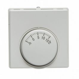
How about if you put the Electronic Thermostat Controller in line with one of PV cables? Cutting any solar charging power to the battery when set at the desired low temp? Or inline with your AC charger?

Would this be a problem and any input as to if this could work. :unsure: :unsure:
Yes, this would work - only with the limitation that the thermostat controller's "load" Relay must support both the maximum Voltage (Voc) and maximum current of the Solar Array. In the more general case, which I *WILL* use if my SCC cannot withstand lengthy disconnection from the battery bank, you and I can use a "NC" Relay connection to leave the solar connected whenever the Thermostat Controller has not activated its load terminal.

Although this gets super complicated and super-long, here's what I will have if the SCC must remain connected to the batteries all the time (i.e. all the way through a long, cold night):

The thermostat controller has a permanent "+12v" connected on one relay terminal, while the other terminal leads to the coil "+" terminal on a 5-pin automotive relay. The Solar Array "PV +" comes in on terminal pin 30. It's connected to pin 87 whenever this secondary relay's coil is NOT activated. When the coil is activated by the thermostat relay calling for heat (and solar disconnection), pin 87 is disconnected from pin 30 - and pin 87a is "connected " to pin 30 instead. But in the Relay socket, we have connected pin 87a to absolutely nothing, because the Voltage is too high for running the heater pads.

A different Relay needs to activate the heater pads from the battery itself, and that relay needs to be limited by another control circuit: You probably don't want to keep the battery warm all through the night, using its own energy - so your activation of that switch should depend on both the "low temperature condition" and a timer, starting from (at most) a couple of hours before the Solar Charging day has started, and ending with the end of the charging day.

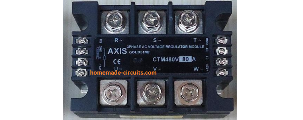
In my RV Solar Configuration, this requires the so-called "automotive Relay" to switch almost 80V on the critical load terminal terminals. But the "High-Current" Relays which I have been using have massive contacts and floating arms, and are already doing that in connection with a closely related application which switches my Solar input leads over here. That auto-switching "Charge from the TV" scheme has been running for many years, with no problems. I'll simply be putting another Relay behind the "switcher" which is already there, adding this temperature-based interrupter one step closer into the "PV +" SCC input.

(Although, in fact, If I go to all of this trouble - I might as well add an additional "auto-switch" Relay for making the batteries warm themselves, when too cold and the "Now charging from TV" circuit has been activated. As soon as they've warmed up, they'll be getting 430 watts of input to charge them back up.) Go ahead and "like" if this made any sense - I think that I've addressed almost everything in this post.
 
I have an idea for building a separate module for low temperature charge protection. In solar systems it may be better to cut power from the panels.
[Optional converter for control circuit voltage>]
DC fridge/ice maker thermostat OR solid state thermal switch > relay(s)

To put the protection on the battery a diode may be needed.
Read my previous post carefully - it includes cutting off the panels, with a relay preceding the "PV +" input to the Solar Charge Controller and cutting it off when the battery is incapable of accepting power (due to low temperatures).

It is based on a switchable fridge/heater thermostat, running as a heater controller. However, I have no idea what you're talking about with a diode. Can you explain its protective function?
 
Relay N/C side without diode for charge+discharge, relay N/O side with diode to only allow discharge
 
Back
Top