diy solar

diy solar

DIY MCI Bus Conversion

DerpsyDoodler

Solar Addict
Joined
Jan 10, 2021
Messages
2,247
Excited to announce I made the purchase of most if my electrical system components.

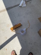
Less than $1700 on (this is whats in the picture):

1x Evo 4024 inverter/charger
1x Evo 4024 remote
1x class t 350a fuse kit
2x class t 200a fuse kits
2x spare 200a fuses
(ordered 2x spare 350a as well, but are on backorder and price of those not included here, though i believe they were 42ish a piece). This was ordered through Don Rowe. The price included UPS ground shipping.
F821FAF4-D257-4C75-8838-22EF8C3583A4.jpeg


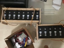
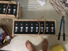
also in that picture are the unfinished boxes for my batteries. The end caps are there and drilled for the threaded rods, the 2x2 sleds are for the bottom, to reinforce the 3/4” plywood and to serve as a place to thread my corded handles through. they will loop over the top, be fitted with vinyl pvc tubing for handles and tie/melted together on the bottom through holes i will drill through the sleds. two handles per box.
 

Attachments

  • image.jpg
    image.jpg
    177.4 KB · Views: 12
Battery boxes are done. Putting together my busbars. The boxes will have weeded lids, as well. I still need to cut the excess threaded rod off. My grinder is at the workshop at the moment.
 

Attachments

  • image.jpg
    image.jpg
    70.8 KB · Views: 29
  • image.jpg
    image.jpg
    70.7 KB · Views: 29
Been a while since i’ve posted. Thought i’d throw out a quick update and a few pics.

Just a pic of the carpentry work i did in replacing the entry ramp with a stepped and leveled entryway.

E00CFE83-B703-4C99-87AA-B152819C73DB.jpeg


A pic of the length to show all the luggage parcels removed, bathroom mostly removed, and windows covered with blackout.

A7E53044-A36B-4791-95A0-552ED4D0BBFA.jpeg

and finally, my house battery disconnect/fuse panel with precharge circuit. the precharge box has a template screwed to the top of it so i can route out around the button, cleaning up the jagged cuts from the hole saw.

37150961-4146-4F6E-BCDE-B8A7D179AC0F.jpeg
 
Here is the battery disconnect panel mounted in its place.

4040C826-5BF0-46B0-A081-47A70B47F6B0.jpeg

Here is the inverter’s home. it is not fastened into place or wired up yet, yet. ac/dc distribution panel also shown.

ADB0DDA5-471A-44FD-89D3-341D33A8005C.jpeg
 
Here’s a few more pics of some progress. the central wall is not yet fastened. the wall that the A/C is mounted on is secured and fastened. Most electrical wiring is complete. I still have a few more circuits to run. The a/c is installed and working.

I powered the inverter up for the first time today. Ran through initial configuration and disabled charging for now. Plugged in shore power to test that entire circuit, all went as planned. currently have shore input limited to 20a draw. with lights, a/c, a bluetooth speaker, and a laptop plugged in, havent seen more than a 12a draw off shore. I am extremely thrilled with these preliminary results!

92FAD974-279F-4A03-B74E-9EF8D8FAA29D.jpeg

B9FF6130-1EEE-4806-B68B-429A6F380B56.jpeg

the big white thing in the middle of the pic is the fresh water tank. its obviously not installed yet, lol. there’s a toilet in the back not installed yet too. Feeling real good about the progress! The lighting arrangement is temporary. just something useable for now. More insulation to be added over the windows, too.
 
Second iteration of battery

B16AB98C-19E9-4568-B63E-5D8B3438B162.jpeg

replaced the bosch style relay with two optocouplers and a small 24vdc-12vdc regulated converter. The whole circuit (including contactor) pulls less than 1/2 an amp (about .41) when energized. the optocouplers only take 5mA to trigger and the contactor itself uses about 1a to trigger and a watt to hold. The dc dc is 3a max and 2 continuous.

Right now, the components are held in place with doublesided 3m, but I'm going to get a small electrical project box to relocate them and the wiring into, as well as add a fuse for the circuit and some small terminal bars to clean up the wiring. I suppose that will make a good place to mount the electrodacus, as well.
 
Last edited:
nice work!

watching this thread for progress as it goes. gigavac contactor, beeg shunt, class-T fuse, nicenice.

may i ask about the wood structure material? historically i've avoided it from concern of water making it conductive on a bad rainy day or something. but of course proper sealing mitigates that, and if there's water in yer box then there's more problems etc.. looks like the components have a separator between the surface anyways. just kinda musing out loud, because i don't know that much in-depth about the properties of various structural materials when used in electricity using installation.

either way i think we all know who the real winner of this project is...

1627848252408.png
 
nice work!

watching this thread for progress as it goes. gigavac contactor, beeg shunt, class-T fuse, nicenice.

may i ask about the wood structure material? historically i've avoided it from concern of water making it conductive on a bad rainy day or something. but of course proper sealing mitigates that, and if there's water in yer box then there's more problems etc.. looks like the components have a separator between the surface anyways. just kinda musing out loud, because i don't know that much in-depth about the properties of various structural materials when used in electricity using installation.

either way i think we all know who the real winner of this project is...

View attachment 58456
Thanks! And yes, he is indeed the mega-winner here. My buddy!

No worries about rain. This is
inside an RV conversion in progress. It's standard plywood (non pressure-treated of course). It's a compression frame. The board behind is the battery disconnect and fuse panel. I have not completed a full fire suppression plan. At the least, I will have a smoke detector and electronics friendly fire extinguisher handy. I will, however, be researching more elegant means of achieving some active (automated) suppression in the battery enclosure. I will be building a cabinet around them, I will also be placing them in some type of tub. Havent found the solution for that, yet.

I'm surprised you're more concerned about plywood becoming a current carrier than the possibility of fire. That said, a ss case seems like a much greater concern of current carrying.

The wood doesnt concern me. I will be performing regular inspections of terminals for tightness and heat before and after road trips. Bad stuff can happen, but there are usually warning signs. (buldging cells, errant/erratic/above or below voltage cells, excessive heat). The cells I got were grade A (at least the closest things i believe these budget commodity cells come to grade A).
 
Thanks for educating’ me, definitely not grilling ya OSHA style ? wood work looks friggin great. ?
 
Thanks for educating’ me, definitely not grilling ya OSHA style ? wood work looks friggin great. ?
Thanks! The wiring is a little messy right now in places, but that's temporary. Some parts I just threw together for testing and interim functionality. Post of my BMS circuit to follow. Would love some feedback about it.
 
lol i was about to anxiously ask you about why the cells were stacked vertically and then i noticed the text on the bar which clued me into the orientation of the photo ???
 
lol i was about to anxiously ask you about why the cells were stacked vertically and then i noticed the text on the bar which clued me into the orientation of the photo ???
LOL...I can see how that might raise concern...lmao. should i fix it? or do you think I should let people freak out until they read your post?
 
Relocated optorelays, regulator, and wiring into the box. added terminal bars and a cooling fan.

View attachment 58617

looks pretty good from here!

(did not analyze circuit layout connections, but curious still)

when working with thin wires and crimps i get anxious about them holding; i’m sure you did a small tug test on the crimps and after screwing down each terminal ?

when i tried to crimp thin wire into pre insulated ring terminals, i failed so many times that it gave me a superstition to solder thin wire connectors but my gut also says soldering is usually overkill for low amp thin wires, tug test should be fine ? /ramble

the only addition i might suggest is maybe a dab of hot melt glue on a few points for wire stress relief (eg box exit)

nice electronics box! ?
I did do the (firm) tug (and wriggle) test. I had to recrimp several times because the connectors i used were meh (they came with the terminal bars). I probably had to toss as many as I used.

All the components I acquired off amazon (including the box), except for the fan. That was from electronic goldmine. I added the fan because the regulator was showing 125f in my thermal imager. When i put my finger on it it didnt feel that hot, though (same with opticouplers). Wondering if the LEDs on the boards were faking out the thermal cam. The fan adds about 200mA consumption to the circuit.

When i had them taped to the top of the battery box, they had no airflow underneath, and the tape may have been insulating the bottom, too (so...*shrug*). When putting them in the box, I still used the doublesided 3-m, but made sure to put it on the board bottoms where it wouldnt insulate any potential hotspots. the boards are also stood off from the bottom of the box and have vent holes drilled (in the box) for airflow around them.
 
Last edited:
Thanks for mentioning relieving cable stress. I dont have a hot glue gun (tossed the last one I had because it just became clutter). It would be good to have and they're cheap, but zip ties on both sides of the through hole serves the purpose. I had them on hand. Perhaps not as visually appealing, but it'll be hidden away in a cabinet. :)

6F1A496E-4636-4A3A-8A1F-CC598F3FAE2E.jpeg
 
So i hardwired the optocouplers closed, put the lid on the box, plugged it in and let it run for an ~hour+. Huge difference in the converter temp. 76f! The optocouplers getting up to 105f, though. Is this normal? I would expect them to stay cooler. they're not pushing current to the low power contactor right now, either.
 
Back
Top