diy solar

diy solar

DIY Peak Shaving?

discreetlyspeaking

New Member
Joined
Nov 7, 2020
Messages
16
Hello,

As an exercise to understand this stuff better, I've been trying to figure out how to build a DIY peak shaver - reducing grid power draw during the day in favor of battery power and use grid power at night to charge batteries when electricity is cheaper. I have a feeling that the answer lies in current or power limiting the grid charger. I found some inexpensive PWM DC motor controllers - would the following below work?
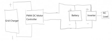
20201117 - Peak Shaving Concept.JPG

I'm also open to something you can buy off the shelf that limits the power output from the grid charger. The grid charger is simply a commercial power supply with voltage control and a maximum current limiter.
 
an all in one inverter is your best option.

my growatt 3kw does grid pass through, includes a grid charger, and you can limit the grid charging current.

You have 2 options, wire up a critical loads panel, or wire up a lockout/transfer switch.
 
Ah looks good! How much control do you have over the grid charging current? I was considering a Mulitplus but depending on which one you get, the grid floor is something around 7-9A.

I've already bought my inverter so still open to other options.
 
I'd be more interested at 14 cents per kilowatt hour from the grid, how long it would take for a system like this to pay for itself.

My batteries alone come out to about $400 per KWh usable storage, which accounts for them being lead acid and not discharging below 50%. If the electricity were free at night, I'd be saving $.28 per $400 of investment every day. So, perhaps in a couple of weeks short of 4 years it would pay for itself and in the fifth year when I've saved $111 real dollars I could get a new battery bank, but more than likely, my rates would be $.10 / KWh at night, so that would mean at the 5 year mark when I need new batteries, I would have saved $146, but have spent $400 worth of batteries, at net loss of 254.

It can be done economically, and I probably screwed my numbers up. As a kid, I got a tour of a powerplant that used electricity at night to fill a reservoir, and in the daytime, they opened to turbines to produce hydroelectric power, and repeated the cycle. Kind of like giant battery. I think it may have been this:https://www.wbur.org/bostonomix/2016/12/02/northfield-mountain-hydroelectric-station
 
I'd be saving $.28 per $400 of investment every day.
I suppose that depends on what your peak rates are. Another person on the forums in AZ i think said they frequenly racked up $100-$150 in peak charges every month.

On my growatt the grid charge current can be set between 10 and 50 amps in i think 1 amp increments (could be every 5).
 
I think the cost and cycle life of batteries make them uneconomical for this, unless utility rate spread is large. Mine spans $0.15 to $0.45/kWh and maybe some batteries could cost $0.20/kWh. Perhaps break-even once electronics is added.

At this time I think it is better to shift consumption, e.g. make ice or heat and charge electric vehicles during off-peak.

Hydro I think is around 50% efficient round trip, so makes sense with $0.04/kWh wholesale but not for the consumer.
I tried to pencil out compressed air but the power vs. pressure and CFM numbers I saw were also down around 50%.

Commercial users and people with punitive demand charges might benefit. (If they use the power daily during peak times maybe not punitive and no benefit, but if peak use one day of the month triggers the cost then batteries could offer a payoff. But so could a generator.
 
I suppose that depends on what your peak rates are. Another person on the forums in AZ i think said they frequenly racked up $100-$150 in peak charges every month.

On my growatt the grid charge current can be set between 10 and 50 amps in i think 1 amp increments (could be every 5).

Yeah, I need something lower than 10A.

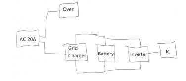
My immediate challenge is sharing a 20A circuit with an oven (15A) and an induction cooker (15A). To simplify the problem, if the oven is off, I want to allow full power access from the circuit (which depends on the power supply) to power the induction cooker. If the oven is on, I'd like to dial down the charger to 3A and pull 12A from the battery to run the induction cooker. When the oven and the induction cooker are off, the charger would fill up the battery at max current for the next round.

I had thought it to be useful to rescope the problem as a utility peak shaving exercise.
 
Tap into the thermostat of one heating device and use it to switch a NC relay carrying power to the other, pre-empting it. They'll take turns.
 
Tap into the thermostat of one heating device and use it to switch a NC relay carrying power to the other, pre-empting it. They'll take turns.
Hmm, not following what you mean. Which heating device are you referring to?

Can anyone comment on whether a DC motor controller can regulate the power charging output to a battery?
 
You listed 15A for oven and 15A for induction cooktop, but only one 20A circuit available. If the thermostat for one cut power to the other, then no more than 15A load at any time.

Similar preemptive control should work for other heavy loads: A/C, air compressor, well pump.
 
Hmm, I'd like to run both at the same time, hence the battery to support the extra load.
Unless both require more than 50% duty ratio, you can still operate both at the same time and get full performance. They just take turns heating and coasting. When first coming up to temperature one will have to wait or the other. After that, they'll just have to "hold it" until the other is done making the transition from thermostat-on temperature to thermostat-off temperature.

Battery can support, but can the inverter? One 20A circuit suggests not. What is the actual power consumption of each appliance? A 20A breaker should have no more than 16A load on it, to avoid nuisance tripping. If inverter can supply both loads at once, just need two circuits with their own breaker. If inverter can't supply both, then find a way to have them take turns every so many seconds or minutes as I suggested, so each remains at desired temperature.
 
The oven and the induction cooker are 1800w each. The oven is hooked directly to the 20A circuit. The induction cooker is hooked to the inverter.

20201120 - Oven and Induction cooker.JPG

When the oven is on, the goal is to power the induction cooker mostly off of the battery with a little assistance from AC outlet (hence the need to dial down the grid charger current draw). The inverter is sized only to support the induction cooker. I'm not sure if the appliances will be really happy about taking turns.
 
Heating elements won't mind taking turns. RF electronics of induction cooker might.

I suggest tapping into thermostat control of induction cooktop and having that interrupt power to electric oven. Or just oven heating element if it has electronic anything that gets reset when power cycles.

No reason for the complexity and cost of charger, battery, inverter.

Now, if you had an inverter/charger which can be programmed to limit power from AC input and supplements with power from battery, you could just put both appliances downstream of it. My SMA Sunny Island SI-6048 would do that, up to 5750W continuous output from battery and programmable input, e.g. 15A from 120V outlet. You'll find them for about $2200 on eBay. That will keep things operating during power failure as well, for as long as battery capacity holds out.
 
Yeah, I don't feel too good about opening up my very very nice induction cooker or oven to achieve what you suggest.

On the complexity and cost - too late, I've already bought the components for the project. This is a fun experiment to learn and at the end of the day, provide utility.

Any comments on whether the DC PWM motor controller can do what you suggest in limiting power from the AC input in DIY fashion?
 
That ought to limit average current, like a PWM charger would.
But its current draw might confuse the AC charger. Maybe a large enough capacitor to smooth out the voltage ripple.
Perhaps just a reduced voltage setpoint of the charger would be better. Or a small enough charger to limit current to 5A, or a resistor (light bulb?) between charger and battery.
 
Back
Top