diy solar

diy solar

DIY questions! - 100+v system to run heating and general appliance in Denmark 10k kwh yearly.

You would have to check the battery specs to see how many you can put in series. Could only be rated for 2 in series. They are usually used in parallel for 48v systems.
Yes ill have to check up on this.
How else do i get a good 20-30 kwh system that is not to expensive and that i can do 10-15kw draws?
 
How else do i get a good 20-30 kwh system that is not to expensive and that i can do 10-15kw draws?

You can draw 15kW from a 48V system. That's 300A - sure, you need a decent connection between your inverter and battery pack, but definitely feasible. With a 304Ah battery pack, this would be 1C draw, so well within its spec. Putting two of them in parallel and you can draw even more.
 
Yes ill have to check up on this.
How else do i get a good 20-30 kwh system that is not to expensive and that i can do 10-15kw draws?

15kW/50V = 300A

One or two forklift batteries (e.g. DC solar trailers some people here have) would do it.
LiFePO4 cells usually have 1C discharge limit. 30 kWh would be 16s2p of 300 Ah LiFePO4 cells (e.g. DIY).
You could instead buy 48V packs (e.g. "server rack" configuration) and parallel them.

Higher voltage vs. lower voltage battery probably doesn't save you money. Same for inverter. 48V systems are a commodity that is readily available so likely to cost less.
 
Why would you not? :) I see them in server racks on youtube quite often :)
As some said above, the batteries are not the problem, it's daisy chaining the BMS that's not such a good idea and I don't think they will recommend building a high voltage battery with their units due to people killing themselves ;)

But theoretically, it should work, and the units should also remain within spec. The voltages over each unit remain the same. And the amps running through each BMS usually remains the same as well. The growatt you listed can only draw 25A anyway:
1645375132816.png

But now we come the actual problem here. What will be the typical loads when operating on battery power only?
In the example of the 10kW version: in order to deliver the 10kW output power from the inverter, you need to draw 10kW of power from the battery... at 25A max current. Which means, we need 400V at minimum to deliver the 10kW and probably even higher due to internal losses and China specs ;)

Perhaps a boost converter could increase the voltage from 48V to ~400V but at that power rating, it would need to be big, and dangerous...
 
As some said above, the batteries are not the problem, it's daisy chaining the BMS that's not such a good idea and I don't think they will recommend building a high voltage battery with their units due to people killing themselves ;)

But theoretically, it should work, and the units should also remain within spec. The voltages over each unit remain the same. And the amps running through each BMS usually remains the same as well. The growatt you listed can only draw 25A anyway:

Batteries or PV panels in series works fine under some conditions, so long as their insulators can withstand elevated voltages above ground. e.g. some PV panels are rated for up to 600V systems, some up to 1000V.

The problems with a BMS would occur when one BMS disconnects, e.g. for over-voltage, under-voltage, or cell imbalance. Or just not turned on at same instant as the others.

If you put four, ~ 50V packs in series and one is open-circuit, it has to hold off the 200V of the itself and the other three batteries.
With one 50V battery opening its FETs or relay, load pulls positive terminal to ground, and the switch has 50V on battery side, 0V on load side.
With four batteries in series, if positive most battery opens its positive connection, load pulls it to zero but positive side of battery is still at 200V, so switch has to hold off 200V.
Similar happens if a different battery opens BMS. If negative most battery, it's positive battery connection is at +50V and when load pull its connection to zero, the negative terminal of battery #2 is driven to -150V. The BMS still has to hold off 200V.

To make this work, I think all disconnects would have to switch together. For instance, a 4PST relay, each contact able to handle the 60V or so open-circuit of the battery. Coil would have to be driven by a signal that is the "AND" of the connect signal from each battery, e.g. four relays in series.
 
Bottom line is stick with a 48v battery system.
Anything above that is considered a commercial installation. And probably a bad idea from a diy standpoint.
 
Why not combine it with an ARK HV battery as it was intended to be? Then it's all compatible within the Growatt ecosystem.
This was my idea for in a few years. When I hope the prices have dropped. But I'm a DIY guy, but messing with HV I tend to avoid.

1645378671244.png

I've attached the product catalog and some price examples from a random Internet shop I found (no relation to me whatsoever) to give you an idea of the cost

1645378859021.png

The prices looks acceptable for the nice conventient design and setup € 0.54 / kWh for the 15.36 kWh (of which 13.81 usable, hence the 0.54).
 

Attachments

  • ARK.pdf
    5.2 MB · Views: 1
Last edited:
To make this work, I think all disconnects would have to switch together. For instance, a 4PST relay, each contact able to handle the 60V or so open-circuit of the battery. Coil would have to be driven by a signal that is the "AND" of the connect signal from each battery, e.g. four relays in series.
Excellent point. Indeed, I didn't account for breakdown voltages. But you could then just as well replace the FET's on the BMS with beafier rated ones up to 400V (edit: actually I'm wrong here after some thinking, the entire PCB needs to be customized for HV) ?
Btw, I've seen the Daly 32S BMS is rated up til 120V, so if you'd take the minimal battery size, just above 100V but below 120V that might work as well.

And I hope the Growatt will have a treshold value under which it won't discharge anymore, so basically the BMS should never 'cut' unless in absolute emergencies or when the inverter didn't do it's job ?

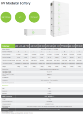
DATASHEET ABOVE
Btw, from the above datasheet it's clear that Growatt is using per 'module' 16 LifePO4 cells of 50Ah in series.
Just some reverse engineering with the numbers shows that.

For the 15.36kWh version I posted above, it's comprised of 6 modules this means: 96 LifePo4 cells combined into a 4800Ah and 307.2V series configuration. I think Growatt just opted for the higher voltage for efficiency reasons and cutting down on the copper size for the power transmission. So they just opted for more lower capacity LifePO4 cells to beef up the voltage, instead of bigger capacity cells to beef up the amps. That means they can also expand later on to bigger modules (200AH+) while keeping the nominal voltages equal.

Edit: and as it's modular, that means that growatt is also daisy chaining their BMS per module?

Did a quick check on AliExpress for both 50AH and 100AH batteries:
96x50AH
15,36 kWh​
€ 3 673,68€ 0,24 / Wh
96x100AH
30,72 kWh​
€ 5 005,68€ 0,16 / Wh
~allows for a 7600W output from the inverter at 25A / 307.2V nominal output which is more than enough if my case.

So, if you pay some good money for a top notch 96s BMS, I think you're golden and have a very nice setup. But also a killer beast if you don't know what you're doing. This thing will arc like sh*t and kill you without hesitation.

Edit2: Found these two BMS's:
- https://www.servovision.com/Battery/BMS Intelligent/Q-3147 Hi Volt BMS Low cos.html -> Video here:
- https://www.servovision.com/Battery/BMS Intelligent/4S to 96S BMS Intelligent BMS4S96S300A.html
both claim high voltage up to 380V and 96S

And this one is the absolute winner IMHO:
- https://www.ennoid.me/bms/gen-1 => but will cost you bigtime :) but rated up to 1000V...

If you have enough by 2500 Watt output power when battery powered, then a 102.4V nominal will work as well by using 32S. You could expand in parallel, but you'll need logic AND's to combine the BMS's outputs so that when one cuts, they all disconnect.
 
Last edited:
Back
Top