MrNatural22
?SW sunshine =⚡️⚡️lit up thru the darkness✌️
Simple inexpensive diy spot welder for smaller battery packs. ?


 diysolarforum.com
How do you adjust the current to avoid blowing holes in the tabs and the cells themselves?I just completed mine based on your example. Works great. Handles .15mm zinc no problem.
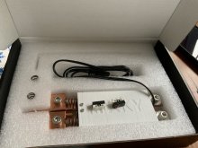
I used this for the pen and switch from Amazon ($22)
This for a secondary switch that I prefer. ($7)
URBEST Black AC 250V 10A SPDT NO NC Momentary Foot Pedal Switch for CNC Industrial with Anti-Skid Rubber Surface: Amazon.com: Industrial & Scientific
URBEST Black AC 250V 10A SPDT NO NC Momentary Foot Pedal Switch for CNC Industrial with Anti-Skid Rubber Surface: Amazon.com: Industrial & Scientificwww.amazon.com
This relay ($13)
A small old 300a AGM battery from my garage and some battery cables. (Free)
Makes perfect, strong welds for under $45 — thanks for the inspiration!
View attachment 29924View attachment 29925View attachment 29923
you typically dont. You vary the "on time" of the momentary switch that you press.How do you adjust the current to avoid blowing holes in the tabs and the cells themselves?
Thanks. I just ordered the three items from Amazon.How do you adjust the current to avoid blowing holes in the tabs and the cells themselves?
I just completed mine based on your example. Works great. Handles .15mm zinc no problem.
I used this for the pen and switch from Amazon ($22)
This for a secondary switch that I prefer. ($7)
URBEST Black AC 250V 10A SPDT NO NC Momentary Foot Pedal Switch for CNC Industrial with Anti-Skid Rubber Surface: Amazon.com: Industrial & Scientific
URBEST Black AC 250V 10A SPDT NO NC Momentary Foot Pedal Switch for CNC Industrial with Anti-Skid Rubber Surface: Amazon.com: Industrial & Scientificwww.amazon.com
This relay ($13)
A small old 300a AGM battery from my garage and some battery cables. (Free)
Makes perfect, strong welds for under $45 — thanks for the inspiration!
View attachment 29924View attachment 29925View attachment 29923

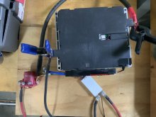
The key to remember is the welder can be either operated by the pen -or- the foot switch. Just a momentary pulse is still you need.
They are both wired in parallel as in the photo below.
If I could only use one method, I would use the foot switch.
The extra micro switches that come with the pen are just spares.
Push down on the pen nibs on a hard surface and you can hear it operate.
Doing so just closes the circuit on the 2 smaller wires.
Is very simple, it just looks a little complex with all the wires. Both switches use red and white wires.
In my version, white wires go to positive on battery, red goes to the solenoid.
When the foot pedal or pen is pressed, power is sent to the solenoid, closing the main circuit on the large wires for the weld.
Is easy to test, just push the pedal, or push the pen on a non conductive surface (ie wood or plastic) and you will hear the big solenoid click into action.
Let me know if you have any other questions.
View attachment 36078


I will draw you out a circuit diagram, give me a moment ....
The small wires from the pen are for operating the solenoid, polarity is not important.
First get the solenoid working when you press the pen down.
Then connect the high power circuits afterwards.
The negative pole on the solenoid is shared with the power and switch circuit, you only need to attach the positive wire to operate the solenoid.
Look at my photos, all the info you need is there, it's much simpler than you think.
View attachment 36219