diy solar

diy solar

DIY SSR

Cal

Solar Addict
Joined
Apr 28, 2020
Messages
752
Actually this DIY project is a high side switch, not SSR. The difference is that a SSR will have ground isolation between the "coil inputs" and the power output. In my case, I don't require isolation. This eliminates an optoisolator.

Im using 6 p-channel mosfets (STP80PF55) wired in parallel to lower the on resistance. The mosfet on resistance spec is 18 mOhm. 6 in parallel should get resistance down to 3 mOhm (in theory).

SwithcSetUp.jpg

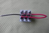
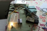
Here's the test setup with 3 mosfets installed on the heatsink. The load is a 2A light. The switch voltage drop is 13 mV. On resistance is 13 mV / 2A = 6.5 mOhm

The mosfets are mounted on a 2x2" heatsink. M3 threads are taped into the heatsink to secure the fets. Due to the heatsink fins, there's no room for nut.

Switch1.jpg

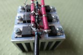
6 mosfets mounted in place. Voltage drop is 7 mV at 2A load, resulting in 3.5 mOhm on resistance. That's pretty good. A small transistor driver board still needs to be mounted to the heatsink.

Switch2.jpg

Each mosfet has its own gate resistor. That decouples the mosfets from each other during switching. There isn't much switching going on so it doesn't matter much if there's switching interference. Switching speed isn't an issue.

I'll be doing some higher amps tests to see what this puppy can do. Heatsink temperature rise is the limiting factor for max current. A 20A load will generate 20^2 * 3.5 mOhm = 1.4 W. A 50A load will generate 9 W. That might be the limit (given the small heatsink size).SwithcSetUp.jpgSwitch1.jpgSwitch2.jpg
 
As you know, they like large sinks.

If you require a large heatsink then using a SSR is the wrong approach. SSR works great for smaller currents, 50A or less. If you want the SSR to conduct 100A then you got the wrong application.

The limit of SSRs is heat. Heat is generated through power dissipation. Power dissipation is equal to the current squared times the on resistance:

P = I^2 * R

In my case on resistance is 3.5 mOhm. At 100A, power dissipation is 35W. That's huge! With I = P/V, the equivalent current "dissipated" is:

I = 35W/13V = 2.7A

You would be a lot better off using a standard relay. Better yet, if you have a 100A load then shut it down at another location (like on/off switch).
 
Pretty cool. I’m using this 500a relay but i drive it with a small n mosfet module. ssrs are cool. The Victron smart battery protect uses mosfets but they blow up when current reverses or high inductive loads. I am not an expert on this stuff. I like playing around with mosfets.
 
  • Like
Reactions: Cal
Srrs modulate though and can do it with precision more or less.
If im not mistaken, ive seen an off the shelf 100A ssr and the only hitch, it they require an adequate heat sink for safety purposes when driven at high duty.
 
Pretty cool. I’m using this 500a relay but i drive it with a small n mosfet module. ssrs are cool. The Victron smart battery protect uses mosfets but they blow up when current reverses or high inductive loads. I am not an expert on this stuff. I like playing around with mosfets.

Hey Danny, you got some nice hardware! I'm interested in your Blue Sea 500A SSR. Could you please measure the voltage drop across the SSR when conducting a sizable current? Record V_dop and current. Thanks.
 
Last edited:
Srrs modulate though and can do it with precision more or less.
If im not mistaken, ive seen an off the shelf 100A ssr and the only hitch, it they require an adequate heat sink for safety purposes when driven at high duty.
I seem to remember mosfets leaking a bit when driven with pwm or a switch? Is that the same for off the shelf ssr? Driving a latching relay with the ssr got me around this issue.
 
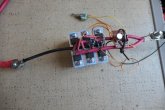
Got some interesting test data. Voltage and current are easy to measure while temperature is a bit more difficult. To measure temperature correctly, I would have to bond a thermocouple to the mosfet, and to the heatsink. I took the easy way out and used a Harbor Freight infrared heat gun. It will have to do. A limiting factor is the use of a 400W MSW inverter to load the DIY SSR. Load current is limited to the inverter capability.

I started out with a 21A load (273W). After 1.5 hours of operation and hardly any temperature increase, I increased the load to 28.5A (370W). After another 1.5 hours at 28.5A the results are:

Voltage drop across switch: 101 mV

ON resistance is: R = 101 mV / 28.5 A = 3.5 mOhm (no difference from previous measurement)

mosfet case temperature = 33.3 C
heatsink temperature = 30.0 C
ambient temperature = 28.9 C

From this data we can calculate the switch capability:

Power dissipation : P = V_drop * I = 101 mV * 28.5A = 2.88 W

mosfet case to ambient thermal resistance: theta_c-a = 33.3 - 28.9 C / 2.88 W = 1.5 C/W
per spec mosfet junction to case thermal resistance is 0.5 C/W
Total thermal resistance: theta_j-a = 1.5 + 0.5 = 2.0 C/W

Per spec, the maximum junction temperature is 150C.
I'll take a guess and say the maximum ambient temperature is 45C (113F)

The maximum mosfet power dissipation is: P = 150 C - 45 C / 2.0 C/W = 52.5 W

SSR max current is: I = sqr(P/R) = sqr(52.5W/3.5 mOhm) = 122 A

If my temperature measurements are reasonable and my analysis is correct then this is a 100A SSR!Switch3.jpg

Switch3.jpg
 
Got some interesting test data. Voltage and current are easy to measure while temperature is a bit more difficult. To measure temperature correctly, I would have to bond a thermocouple to the mosfet, and to the heatsink. I took the easy way out and used a Harbor Freight infrared heat gun. It will have to do. A limiting factor is the use of a 400W MSW inverter to load the DIY SSR. Load current is limited to the inverter capability.

I started out with a 21A load (273W). After 1.5 hours of operation and hardly any temperature increase, I increased the load to 28.5A (370W). After another 1.5 hours at 28.5A the results are:

Voltage drop across switch: 101 mV

ON resistance is: R = 101 mV / 28.5 A = 3.5 mOhm (no difference from previous measurement)

mosfet case temperature = 33.3 C
heatsink temperature = 30.0 C
ambient temperature = 28.9 C

From this data we can calculate the switch capability:

Power dissipation : P = V_drop * I = 101 mV * 28.5A = 2.88 W

mosfet case to ambient thermal resistance: theta_c-a = 33.3 - 28.9 C / 2.88 W = 1.5 C/W
per spec mosfet junction to case thermal resistance is 0.5 C/W
Total thermal resistance: theta_j-a = 1.5 + 0.5 = 2.0 C/W

Per spec, the maximum junction temperature is 150C.
I'll take a guess and say the maximum ambient temperature is 45C (113F)

The maximum mosfet power dissipation is: P = 150 C - 45 C / 2.0 C/W = 52.5 W

SSR max current is: I = sqr(P/R) = sqr(52.5W/3.5 mOhm) = 122 A

If my temperature measurements are reasonable and my analysis is correct then this is a 100A SSR!View attachment 13576

Switch3.jpg
Is there a curve, or is it linear across the rise in current output to max theoretical?
 
Mostly linear but the Rdson tends to rise with temperature so the curve rises a bit faster at high currents than low currents.
 
Its to be expected. A point of diminishing returns to increasing flow, switch cycle or what have you. Elecrronically i dont know much about.it. hardware wise, its always been a caution that an ssr or mechanical relay or contactor needs generous overhead or they become a fire hazard.

Many folk with either fond that the rating is lacking or that the heatsink for an ssr did not provide enough dissipation to allow near max continuous output.

A friend of mine builds control panels for greenhouse and indoor grow controllers...... has had several relays zorch up amd melt down.

 
Last edited:
Mostly linear but the Rdson tends to rise with temperature so the curve rises a bit faster at high currents than low currents.

It's actually a good thing that Rdson rises with temperature. Because of the positive temperature coefficient, parallel mosfets share current reasonable well. There's no thermal runaway.

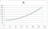
In regards to the question if there's a curve or if it's linear. It is not linear since power dissipation is: P = I^2 * Ron. Power dissipation increases with current squared. Everything boils down to fet junction temperature. Rule of thumb, every 10C rise in temperature doubles the failure rate of the device. We want to keep junction temperature at a minimum. Here's a graph of junction temperature as a function of current. Ambient temperature is 45C (113F).

x-axis = current
y-axis = fet temperature

At 80A fet temperatures rises by 40C above ambient. That might be a reasonable limit for this SSR.

TjVsI.jpg
 
"Rule of thumb, every 10C rise in temperature doubles the failure rate of the device. We want to keep junction temperature at a minimum. Here's a graph of junction temperature as a function of current. Ambient temperature is 45C (113F)."

Love your detailed explanations! Thats the stuff. And illustrates why we de-rate these devices heavily and provide planty of heat sink.
 
another challenge in battery BMS applications is that MOSFETs have inherent body diodes, which makes it always conduct (poorly) in the opposite direction, so if you need to protect the battery from charge and discharge, then you must double number of FETs and place half of them biased in opposite direction, which doubles losses and BOM costs. Gate driving also becomes more complicated.
Thanks for sharing a fun DIY learning project.
 
this also shows you why P-channel FETs are rarely used in power applications. N-channel is much more efficient due to lower Rdson, but gate driving requires a charge pump.
 
another challenge in battery BMS applications is that MOSFETs have inherent body diodes, which makes it always conduct (poorly) in the opposite direction, so if you need to protect the battery from charge and discharge, then you must double number of FETs and place half of them biased in opposite direction, which doubles losses and BOM costs. Gate driving also becomes more complicated.
Thanks for sharing a fun DIY learning project.

Well that's the fallacy of a one port battery. Both charge and discharge current go through the same wire. The switch requires current to travel both ways, making it very complicated. That's what "drop in" LiFePO4 batteries like Battleborn are up against. Their battery resistance is about 10 mOhms, equivalent to AGM batteries. My 180AH 12V CALB battery has about 6 to 7 mOhm resistance. Battleborn max current ratings are limited by the mosfets inside their case. And it's not easy getting the heat out of there. Don't see any protruding heatsinks!

I don't need a high current switch to disable charging sources (solar, alternator via dc/dc and Iota converter). Those are accomplished with low current signals.

This is going to be way overkill as I'm going to install this diy SSR in my secondary camper ('91 VW Westfalia). I just replaced the stock propane fridge with an electric one. Hence the reason for LiFePO4. Load current is about 3 - 4A.
 
Just about no one uses P FET. I use N FET on the high side. I had one that was cobbed up quick and used just a battery and opto isolator because it wasn't switched on and off fast. Two years later still hadn't got around to updating it and the battery still hadn't dropped down in voltage. Many 120V AC switching supplies work at just 60V DC at low power. I buy these for $1.50 shipped, aways keep a dozen of them in the shop.
 
It's actually a good thing that Rdson rises with temperature. Because of the positive temperature coefficient, parallel mosfets share current reasonable well. There's no thermal runaway.

In regards to the question if there's a curve or if it's linear. It is not linear since power dissipation is: P = I^2 * Ron. Power dissipation increases with current squared. Everything boils down to fet junction temperature. Rule of thumb, every 10C rise in temperature doubles the failure rate of the device. We want to keep junction temperature at a minimum. Here's a graph of junction temperature as a function of current. Ambient temperature is 45C (113F).

x-axis = current
y-axis = fet temperature

At 80A fet temperatures rises by 40C above ambient. That might be a reasonable limit for this SSR.

View attachment 13696
The sweet spot seems to be right in the middle of the sweep in temp amd current leaving overhead and preserving safety and efficiency.
 
Just about no one uses P FET. I use N FET on the high side. I had one that was cobbed up quick and used just a battery and opto isolator because it wasn't switched on and off fast. Two years later still hadn't got around to updating it and the battery still hadn't dropped down in voltage. Many 120V AC switching supplies work at just 60V DC at low power. I buy these for $1.50 shipped, aways keep a dozen of them in the shop.

No doubt N-channel fets have better specs. The KISS principle led me to use P-channel. If P-channel fets meet ones goals then there's no reason to use N-channel.

It takes some engineering to design the charge pump as gate current becomes significant during switching (due to Miller capacitance).

You want to share your high side switch schematic?
 
Just use a low current isolated DC/DC converter and some caps. The gate capacitance is pretty low so you don't need a lot of caps for that, 10x or more is fine ;)

Also, if switching speed isn't important (and here it's not, unless you have a very specific application) you don't really care if it takes a bit longer to close/open the switch (and we're talking difference in µs to ms at most) so you don't even need to add bulk caps, a simple 50 or 100 mA DC/DC converter is good enough on its own. It can actually be better to switch slower to avoid transients and EMI.

So that and an isolated gate driver (the 1EDI60N12AF is very nice, lots of built-in safeties and features, under 2$) and you're good to go ;)

If you really really don't care about switching speed and want to save 2$ you can even use the DC/DC converter on it's own but I don't recommend that, especially for beginners, there's some traps.
 
Back
Top