diy solar

diy solar

Do I need a breaker?

CReborn

New Member
Joined
Jun 20, 2021
Messages
19
I just realised, that after exchanging my old inverter with a built in circuit breaker (400W with a 40A breaker) with a new 1000W inverter (NV - P1000) which has:

Electronic overload protection with automatic shutdown.
Built-in internal backup DC fuse provides added safety.
Low battery voltage warning followed by automatic shutdown.
High input voltage protection with automatic shutdown.
Over temperature protection with automatic shutdown.
Output short circuit protection.

Do I need another circuit breaker? If so.. where? At the 220V side.. or at the 12V side? How strong? The inverter specs say it gives out 9A at 220V. Should I use a 10A fuse? I believe the electronic protection will kick in much sooner... At 1000W power... that would be 80A on the 12V side. Do I need to put a 80A breaker... or just put a 32A (limiting the output.. which is way below rated 1000W. The biggest surges come from starting the water cooler (60W) and a freezer.. possibly a small 90W water pump. Nothing works constantly.. only for a few minutes on and off...

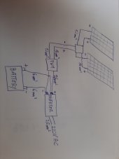
I realised I haven't given you any specs of my system:
130W panels (2 in parallel, 16A max for both)
10mm2 wire (negative is 10mm2, positive is 16mm2) rated at 60A connecting the panels and the 20A PWM controller. The batteries are connected with a 6mm2 wire (44A rating) to the inverter, and 2,5mm2 (I believe.. or maybe 4mm2) rated at 25A from the PWM to the inverter (only around 50cm long). The battery connection on the inverter, and the PWM connection to the battery is shared on the same inverter terminals. That's how it was connected before.. only with thinner wires, and older components...

Where do I need to put a breaker, if any, and what size..

Thank you
 
Last edited:
You need fuses or breakers to protect the cables. The battery is the power source , protection, fuses or breakers are needed at the battery positive terminal. 6mm2 cable is good for 50 amps so must be fused at or below that.

However the cable is not suitable for a 1000 watt inverter ( it will take around 90 amps, perhaps more on short term overloads) you need at least 16mm2 cable, and to minimize volt drops, 25mm2 cable would be better.
This would need a fuse or breaker at the battery rated at least 100 amps, perhaps 125 amps, or 150 amps.

The 2.5mm2 cable from the PWM should be connected to the battery via a 25 amp fuse/breaker at the battery. This cable is somewhat under size and will introduce volt drops.

The inverter output at 220 volts with permanently connected to appliances may need AC protective devices to prevent electric shock. This depends on the application, country and local regulations. The inverter instructions should identify if it has a neutral to earth bond. If this is the case you may/will need a double pole RCBOor RCD on the inverter output before its connected to the 220v distribution circuit.

Mike
 
Nothing works constantly.. only for a few minutes on and off
That may be a problem. The inverter idle mode may put it to sleep without a constant load.
Needs further input by a inverter expert- What do heavy startup loads do to modern inverters or equipment awakening from idle?
Will modern equipment, water coolers, with their electronics, be able to start idle inverters?

As for the original question ' do I need a breaker?'
No. Because that short length of wire between battery and inverter should be routed so that no heat damage can occur to surrounding surfaces in case of failure and any fuses blowing in the confined battery space adds their own particular hazard.
 
As for the original question ' do I need a breaker?'
No. Because that short length of wire between battery and inverter should be routed so that no heat damage can occur to surrounding surfaces in case of failure and any fuses blowing in the confined battery space adds their own particular hazard.

You must be kidding.

When the short length of wire catches fire due to a catastrophic problem the sh!t will hit the fan.

A breaker would avoid the fire and a quality fuse does NOT cause more problems than it solves.
 
OK.. so I can use the 6mm2 wire as a connection from the PWM to the battery. Add a 25A circuit breaker to protect that.. and I could get a 16mm2 (25mm2 really sounds a lot, but if available at my company, I can get that too...) for the inverter-battery connection. The funny thing is .. the cables are thicker than the inverter terminals (6mm screw). Especially since the wires are stranded, not solid.. giving them bulkier look. Not sure where to get a 120A circuit breaker.. or simply use a fuse... I have those in abundance...
 

"Interrupting Rating: 2000A @ 32 VDC"

What kind of battery do you have? Link to data sheet?
A car battery can deliver 3000A into a short. AGM, 4000A. LiFePO4 battery, I think 20,000A (based on the internal resistance ratings I've seen.)
There are other fuses rated 5000A, 10,000A, 20,000A AIC which could be appropriate for various batteries.

As for the AC side, inverter will never deliver enough current to overheat a 14 awg wire so no need.
If you do use a fuse or breaker it should be 25% larger than inverter's continuous output (and no larger than wire rating.)
 
battery:
TAXXON TRUCK 180Ah 1100A (1100A being the startup current).
 
battery:
TAXXON TRUCK 180Ah 1100A (1100A being the startup current).

Starting current about 50% higher than a large car battery, so maybe 5000A short circuit current.
A fuse like this one has sufficient AIC rating


Or this, lower but sufficient


Hmm, the Littlefuse Midi only said 2000A at 32V, but Blue Sea also says 5000A at 16V

But the Mega only lists the 2000A figure


"Interrupting Rating: 2000A @ 32 VDC"

What kind of battery do you have? Link to data sheet?
A car battery can deliver 3000A into a short. AGM, 4000A. LiFePO4 battery, I think 20,000A (based on the internal resistance ratings I've seen.)
There are other fuses rated 5000A, 10,000A, 20,000A AIC which could be appropriate for various batteries.

As for the AC side, inverter will never deliver enough current to overheat a 14 awg wire so no need.
If you do use a fuse or breaker it should be 25% larger than inverter's continuous output (and no larger than wire rating.)
As we say in electronics : the transistor is there to protect the fuse. If one looks at the time / current graphs it takes about 150 amps to blow a 40 amp fuse in 1 sec. Will it not be more prudent to rate the fuse only 10% higher than the max current expected ? I have seen melting wire insulation with high amperage fuses due to the ‘trip’ delay.
 
So... a recap.

Would this be a good solution:
Do panels need any breakers since they are 8A SCC?. Connected in parallel, they give out maximum of 16A. Should I place one 20A breaker just before the PWM.. Or do I put 10A breakers on each panel? Not sure what is the purpose, since they can't do any damage when short circuited, and if the PWM goes into a short, the breaker between the PWm and the battery will react...
I have replaced the thin 2,5mm2 with a strained 10mm2 wires directly from the controller to the battery. I plan to put a 20A breaker between the PWM and the battery, since the pwm controller is 20A. I have ordered a 150A fuse for the "+" wire of the battery - inverter connection,and I plan to exchange it for a 16 or 25mm2 strained wire.
Sounds good. I would not bother with any fuses / breakers in the lines from the PV panels to the PWM. The more joins you have the greater the possibility for connections going bad resulting in losses etc. Go with the heavier wire between battery bank and inverter - at least 16mm2 depending on the distance.
 
When the short length of wire catches fire due to a catastrophic problem the sh!t will hit the fan.
I guess each person must do their own risk analysis for their own particular systems taking account of any failures in the design where a overheated wire can lead to such an event.
 
I guess each person must do their own risk analysis for their own particular systems taking account of any failures in the design where a overheated wire can lead to such an event.
Agreed but recommending people NOT use OCPD on an inverter circuit is just unsafe system design and implementation. Period.
 
As we say in electronics : the transistor is there to protect the fuse. If one looks at the time / current graphs it takes about 150 amps to blow a 40 amp fuse in 1 sec. Will it not be more prudent to rate the fuse only 10% higher than the max current expected ? I have seen melting wire insulation with high amperage fuses due to the ‘trip’ delay.

Was that with wire/insulation/bundling having ampacity equal or greater than breaker rating, and a UL (or equivalent) listed breaker?

I've read that over-current trip of breakers does overheat the wire, but should be good for about 100 trips before insulation is excessively damaged. The code requirement of 20A max OCP for 12 awg (ampacity 30A) gives considerable margin for household convenience outlets.

Prudent? Code requires 25% higher than max continuous current.

Trip curves vary, could be selected according to brief overloads expected and protection required.

So... a recap.

Would this be a good solution:
Do panels need any breakers since they are 8A SCC?. Connected in parallel, they give out maximum of 16A. Should I place one 20A breaker just before the PWM.. Or do I put 10A breakers on each panel? Not sure what is the purpose, since they can't do any damage when short circuited, and if the PWM goes into a short, the breaker between the PWm and the battery will react...
I have replaced the thin 2,5mm2 with a strained 10mm2 wires directly from the controller to the battery. I plan to put a 20A breaker between the PWM and the battery, since the pwm controller is 20A. I have ordered a 150A fuse for the "+" wire of the battery - inverter connection,and I plan to exchange it for a 16 or 25mm2 strained wire.

Two PV strings in parallel do not require OCP, because at most the Isc of a single string goes through any given wire (of the PV strings.) The home run wire needs to be sized to carry 2x Isc. For both the string wires and the home run, sizing requirement is 1.56x the current. That's the usual 1.25x to avoid nuisance tripping, and another 1.25x because some lighting conditions can produce more than Isc from a panel.

OCP should also be sized 1.56x Isc. (2x 1.56x Isc for home run of to combined strings.) Of course, wire ampacity must be at least as high as OCP.

So 20A breaker is below recommendation for 16A Isc of array. It would be the correct 1.25x for a 16A charge controller to battery. 25A would be recommended OCP for 16A Isc array.

20A controller, should have 25A OCP. (just so happens to be same as for PV array in this case.)

10 mm^2 is about 7 awg, rated for about 65A in a cable (if 90 degree insulation) so seems quite good.

16 mm^2 5 awg 85A (in a cable), 125A (in free air)
25 mm^2 3 awg 110A (in a cable), 155A (in free air)

For 150A fuse I would go for 25 mm^2 not 16 mm^2 wire.


Maybe the NV P 1000 comes with a 6mm2 cable FOR the voltage drop under high loads reducing the V down to the cut-out voltage of 10volts as an extra safety protection??

I have a different theory: ???
 
I cannot understand why anyone should suggest that over current protection is not needed. I agree that fusing the panel feed is not needed, but any cable connected to the battery needs a suitable fuse/breaker.
Outside the US suitable breakers are expensive and the E bay/Amazon offerings are usually poor quality.
Fuses are reliable and not too expensive.

The low cost inverter is perhaps not able to power the loads even with suitable cable. Although sold as a 1000vwatt unit there is a high chance it will, in practice, not be able to deliver this. Powering a freezer compressor is a demanding task for an inverter, requiring a good overload capability.

I am still concerned that there is no provision for protection on the 220 ac side. Once you have a distributed system with metal bodied appliances and water in the mix, there is an increased risk of electric shock.

Mike
 
Last edited:
Back
Top