diy solar

diy solar

Do LFP produce heat with discharge?

Can you send me a pic of the configuration or described it.

This is the battery box (picture before insulation):


I then just have the heating pad coupled to a block of aluminium (doesn't even have to be in any particular place in the box) controlled by the thermostat (the ones I mention in #7). That's it really.
 
Good to know, how many pads are you using? How big is your battery bank if you don’t have a 12 V system how do you tie them in? I was kind of thinking about using something like this below it seems only be around 20 White’Good to know, how many pads are you using? How big is your battery bank if you don’t have a 12 V system how do you tie them in? I was kind of thinking about using something like this below and gives me really good temperature control
The 2 mats will allow the calls to sit enteral on them or on the side


I've got a 2p4s 12-volt bank utilizing 8 EVE 230s. I'm using four of the little heating elements stuck to an aluminum plate to spread the heat. At only 28 W, it heats the pack pretty gently.
 
I then just have the heating pad coupled to a block of aluminium (doesn't even have to be in any particular place in the box) controlled by the thermostat (the ones I mention in #7). That's it really.
Wow, that is a great looking install! Well done. So it looks to me like that is a 16 S battery. Is that correct. If so that is what I will be building.
Another question on that aluminum block. How big a block are we talking? It sounds like most folks are putting an aluminum sheet underneath their batteries. But you said you just put it anywhere in the box.
Also if that’s a 16 s i’m guessing that’s making it a 48 V system do you have a recommended DC to DC converter to bring down the voltage to 12 bolts for the heating pad.

One last thing what sort of fuse is that that you are running. I would like to get one of those.

Is your s a 100am bms?

Sorry for all the questions truly appreciate the help!
 
(2) 8s (long) DYI batteries with plate and compression rods sit side by side lengthwise
A seed starting heating pad sits on edge between the batteries. (with temp controller off to the side)
From it sounds like it’s certainly the sort of system I was thinking about doing. I was thinking about using my own ink bird controller as opposed to the ones that come with it so I could set the heating pad to a cooler temperature
Question, so you don’t mind running it on AC through your inverter versus direct DC like other folks or talking about.

Thanks so much for the invite I’m starting to get my head wrapped around all this:)
 
You picked a good time to chat about keeping your batteries warm.
There were quite a few -20s F, -30s C in Northeast Wyoming last night.

Todays high will be about 10 F, -12 C. Yaa Freakin Hoo!
 
So it looks to me like that is a 16 S battery. Is that correct.

Yes.

How big a block are we talking?

I don't have the exact dimensions, just something big enough to act as a heat spreader for that heating pad - it needs to be coupled to something. If it's too small, it gets too hot. At the time, I just used what I had around and did some tests.

It sounds like most folks are putting an aluminum sheet underneath their batteries. But you said you just put it anywhere in the box.

Both ways are fine. I have one other box where the heating is done from the bottom, with a sheet of aluminium.

Also if that’s a 16 s i’m guessing that’s making it a 48 V system do you have a recommended DC to DC converter to bring down the voltage to 12 bolts for the heating pad.

Made my own, but something like this or similar should do fine:

One last thing what sort of fuse is that that you are running. I would like to get one of those.

Class-T 225A on that one. You really want Class T with anything Lithium, especially at 48V.

Is your s a 100am bms?

Yes, JK/Heltec 100A version. I have a larger one should I ever need it, but haven't yet.

Sorry for all the questions truly appreciate the help!

No problem - ask away :)
 
From it sounds like it’s certainly the sort of system I was thinking about doing. I was thinking about using my own ink bird controller as opposed to the ones that come with it so I could set the heating pad to a cooler temperature
Question, so you don’t mind running it on AC through your inverter versus direct DC like other folks or talking about.

Thanks so much for the invite I’m starting to get my head wrapped around all this:)
I slapped together the heating from what I had laying around. Cold weather was upon me by the time I finished building my batteries and it was meant to be temporary until I did something like upnorthandpersonal. But it has proved to be more than adequate so I haven't even thought about buying the upnorth parts.

The seed starting pad I really like - no need to glue it to a metal sheet. And with a good insulated box keeping the heat I see no reason to place it under the cells. The pad actually puts out heat from both sides. I have temp sensors on the "inside" between the packs and on the "outside" - temp difference is about 4F. The inside probes are close enough to feel the heat coming off the pad. The outside probes are a good reading of the box temp - they are less than a degree off of each other

I have no problem with using power on the AC side of the inverter.
Heat pad and controller uses about 21w. I expected the pad to shut off at my set temp (58F) but it hasn't so I'm using 530w per day according to my Kill A Watt meter.

Further description of my system:
It was meant to be a backup but I hated to see all the potential energy from 1560w PV array go unused.
I have added a Moes ATS to use some of the capacity of my battery bank. (set a low voltage to switch to grid and back to solar with a higher voltage) The voltage setting to switch to grid is high enough to reserve most of the bank's capacity. (26.6v) I'll lower that when the sun do shine after the dark days of winter.

I haven't seen the sun in 7 days. My inverter uses 25w regardless of using the grid or not. But even on overcast days I'm making enough power to keep the battery bank voltage fairly constant.

without the ATS:
I'm pushing 1200w daily usage with just the inverter and heating pad. With a 9600Wh bank I'd have 8 days (100% discharge) in total darkness.
Given some sun I can make that and enough to run my aquariums (while keeping a reserve for grid down)

It's a given that the constant pad on isn't going to work for those with a small battery capacity but it's a workable if not ideal setup with a large bank.
 
-20s F, -30s C in Northeast Wyoming last night.

Todays high will be about 10 F, -12 C. Yaa Freakin Hoo!
Yup it’s been chilly but makes up for the crazy warm start of winter we had.
Nothing like when we lived Pinedale way.
Actually Boulder. That was a cold spot.
 
I have averaged -13C external ambient for the last three weeks with dips into the -18 on three separate days/cycles. I have an aluminum plate that is 8mm on the bottom along with the long sides that have a total of 16 of the 25 watt heating pads spaced 8 on the bottom and 4 on each side.

Bottom is wired series parallel and the sides are series. this tied into a temp controller with two remote probes (center of pack 2" from the bottom and one 3/4 of the way from the bottom.) These are set for an 8C-15C cycle and enclosed on top and bottom and all sides with 50mm of the blue XPS foam.

It keeps the temps between a low of 7C and a high of 18C as measured with a perfect prime 4 probe temp datalogger.

I have a total of 4 (four) temp probes for the data logger.
3 (three) for the BMS (1 Each).
4 (four) for the solar controllers (one each).
One (1) for the inverter.

Total temp probes are twelve (12) each agree within reasonable standards. the probes are situated in different locations to include the bottom of the battery pack, the sides, a couple of the middle and five at the top for the SCC's and inverter scattered across the cells. so data is pretty conclusive.

batteries are at a safe temp the entire time and the total draw is minor compared to the size of the battery bank.
 
The packaging that my EVE 280aH cells came in looks to be about as good as can be had for an insulator. Maybe use that. I would think spray foam might be good too.
 
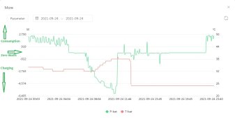
I don't know if this helps but it is a graph produced by PV-Pro that shows how my battery temp changes (Red Line) during a selected day. I put some Arrows and notes on the left to clarify what you are seeing.
As you can see during Charging they get twice as hot as when your pulling power from them.

BatPowerVsTemp.jpg
 
Maybe this is dumb question. But with my BMS being 100 amp. Wouldn’t I want a 100amp fuse+\- Not 225?
The reason (as far as I am concerned) for the Class T is to protect in an extreme overcurrent event. If your inverter smokes the class T fuse will limit the energy involved in the event. Large semiconductor modules will disintegrate and release plasma. It's like a small piece of the sun right here on earth. The Class T will keep the damage to a minimum and in most cases will prevent the semiconductor module from rupturing.

I am using 125A BMS with a 200A class T fuse and a 65A breaker with 2 poles wired in parallel for 130A. The breaker is used to protect the wire.

I looked at smaller Class T fuse, but they would not survive the inrush event at power up without an inrush limiter circuit.
 
Maybe this is dumb question. But with my BMS being 100 amp. Wouldn’t I want a 100amp fuse+\- Not 225?

My BMS is also 100A, but it can surge more than that for a limited amount of time. If there is a case where you have e.g. a short, the fuse will blow before the BMS gets damaged. If there is just a higher current for whatever reason, say 150A, the BMS will turn off because of overcurrent protection in the BMS and not take the fuse out.
 
fuse for your wiring, not your equipment. I am not familiar with the NEC requirements, but I have worked around electricity enough over the years, both AC and DC to know that some of those rules are in place for a reason.

Imagine this.... It is 1998. you have an award winning SPL demo van running in the 600 watt class. (2nd in all of Japan BTW) you are of course running cheater amps... two Orion 2100 HCCA's to be exact. (plus amps for your mids and highs).

Stock they come with two 60 amp AGU glass fuses internal on their board (two per amp) .... as a competitor you off course remove them and insert 100 amp AGU fuse's, wrapped with aluminum foil in their place, (before you twitch anything less than winning is losing...) This is to give you an idea of what kind of power they run continuously at 12 volts. (14.4 optimal)

you have 10 optima red tops in parallel along with 6 one farad caps to stiffen up your amps.... your co-worker while cleaning the demo car removes the primary power cord (004 aught power cable) from the battery pack and in an instance of stupidity allows it to fall out of his grip and onto the main negative buss bar. ever seen 004 aught power cable explode? nope neither have I , (but I sure as hell heard it!) I had to call the ambulance so that idiot boy could get a ride to the hospital and get the copper fragments removed from his arm, face and his left eye. it happened so fast that even with the class T fuses that were inline for the system, it still blew the 004 aught cable apart and caused the remnants to melt in mid air to end up embedded in my co-workers arm and face. (no lasting damage to his eyes thank the lord). but it goes to show that even at 12 volts the amount of amperage we are playing with is stupid.... STUPID. lets not talk about 48 volt systems.

so I typed all this just to let you know, the fuses are not there to protect your equipment, they are there to protect the wiring so that you do not get a fire started in a wall somewhere for any of the myriad reasons that could cause a wire to overheat. not to mention stupid co-workers that drop the positive wire onto the negative buss bar on 10 optima's and 6 stiffening caps.

cheers

Ken
 
Back
Top