That is the exact opposite of what my battery manufacturer has told me.
My notes with regards to current tapering are in line with a CC-only charge cycle with a balance phase (as short a CV as possible) and switch to a float. I can, however, see I didn't fully explain my point and I didn't word it correctly. Thanks
@toms for pointing that out. Plus on my side, we've changed our parameters/targets over time and become a little more detailed about things as more lab testing has been done/published. Even different than some parameters/targets I have mentioned in the past.
The charge current of any lithium cell, and even lead acid , does need to taper down as the cells reach their maximum voltage. Th Constant Voltage part of the charge cycle.
This is what is interesting and can also be confusing to some people. I'm not meaning this towards you
@GXMnow in any way, just commenting in general. Once we reach the voltage target, let's say 3.45VPC, and we hold that current, the current will begin to taper off until the charge termination parameters are met. This is very true! CC-CV charging.
However, by nature of the low IR of the cells and the low capacity of most balancing circuits, the current can at times still be too high for the balancer IMHO. This is not always the case if, for example, you're already charging at an extremely low current. The real key here though is that charge termination at target voltage will increase the usable capacity over the lifespan of the cells, hence the reason to taper charging to the absolute minimum while to balancing to termination. The longer one holds at the target voltage and continues with the constant voltage stage, the larger the solid electrolyte interphase (SEI) grows, thereby reducing the usable capacity of the cell.
Having high current balancers is extremely useful here because it helps to reduce the balancing time, thereby reducing the amount of time the cell is held at the target voltage.
Here are a few comments from a whitepaper discussing capacity degradation with PHEV and EV applications:
Source:
Model-Based SEI Layer Growth and Capacity Fade Analysis for EV and PHEV Batteries and Drive Cycles
"Passive SEI layer growth is a major contributor to capacity fade in Li-ion batteries used for EV and PHEV applications. The majority of SEI layer growth will occur during charging. While fast charging creates undesired stress and temperature affects among other degradation problems, it will limit the amount of direct SEI layer growth in comparison to slow rates. Additionally, CC-CV charging will increase the amount of charge stored within a battery for a single cycle, but over the entire cycle life of the battery will decrease the total amount of usable energy from the battery for drive cycle cases."

Note that C2 results in the lowest SEI growth.
"Most charging applications apply a constant current charge followed by a constant voltage charge (CC-CV). While this protocol maximizes the amount of charge stored for a single cycle, the CV portion of charging greatly increases the charging time while adding stored charge at a diminishing rate. The increased charging time will lead to increased SEI growth. CV charging only occurs during the end of the charging cycle and at high levels of SOC. Figure 1 (above) shows that during the CV portion of charging the rate of SEI growth with respect to charge stored increases for all cases. Previous experimental studies have shown that increasing the portion of CV charging can lead to increased capacity fade. In cases where an EV owner is willing to forego the additional charge stored from CV charging (less than 10% in most cases), they will see a benefit over the life of the battery by reducing the SEI growth. Other degradation effects may negate the benefit of CC only charging."
So in many ways, switching to a float at the end of a CC cycle works well for retaining capacity. Hence my thoughts on reducing charging current during balancing to just enough to balance and then switching to a float, using a shunt to help ensure zero current flow into the batteries during float.
With a BMS without communication, here is what
can happen with slightly mismatched cells. I'm NOT saying it does happen, I'm just saying IMHO we want to avoid it.
When we reach 55.2V in a 16S bank (3.45VPC target for example), we could begin constant voltage and the current will being to taper, if a person is using CC-CV. However, when we reach 55.2V, there is simply no way of knowing if all cells are at 3.45V or if any of them have
exceeded 3.45V while yet being under the trip limit which is likely farther up into the curve (3.65V etc). Beyond that, most have a hysteresis beyond the trip limit (3.65V etc) so they don't trip in a passing spike. This is where it gets tricky IMHO.
IMHO we do not want to ever exceed 3.45V or whatever the target voltage may be. Essentially stay out of the curve as much as we can. We don't want cells exceeding the target and then waiting to come down while the balancer balances. We want to instead reduce current dynamically to a place where no single cell ever exceeds the target, keeping the incoming current low enough to allow the balancer to do its work.
One of the reasons for this to prevent the expansion of the cell as much as possible which can reduce the thickness of the SEI barrier and allow electrons to tunnel through the SEI barrier, breaking down the electrolyte. Expansion grows with the increase in cell voltage
and SOC. This is where cell compression helps to reduce cell capacity reduction by reducing the amount of physical expansion.
@the_colorist would you recommend getting the optional monitor? It's $215 I think but if the Can communication is going to work OK and the unit comes ready to go, will I need that monitor?
As for contactor, I believe the one they have listed on their site is pretty heavy duty, (800v, 400a). Would I need that, or is something like
this sufficient?
I would recommend it. It's great for adjusting settings as time moves forward and perhaps we learn more about how to prevent cell capacity degradation. It's also the only way to see cell voltages. There isn't an app or wireless access.
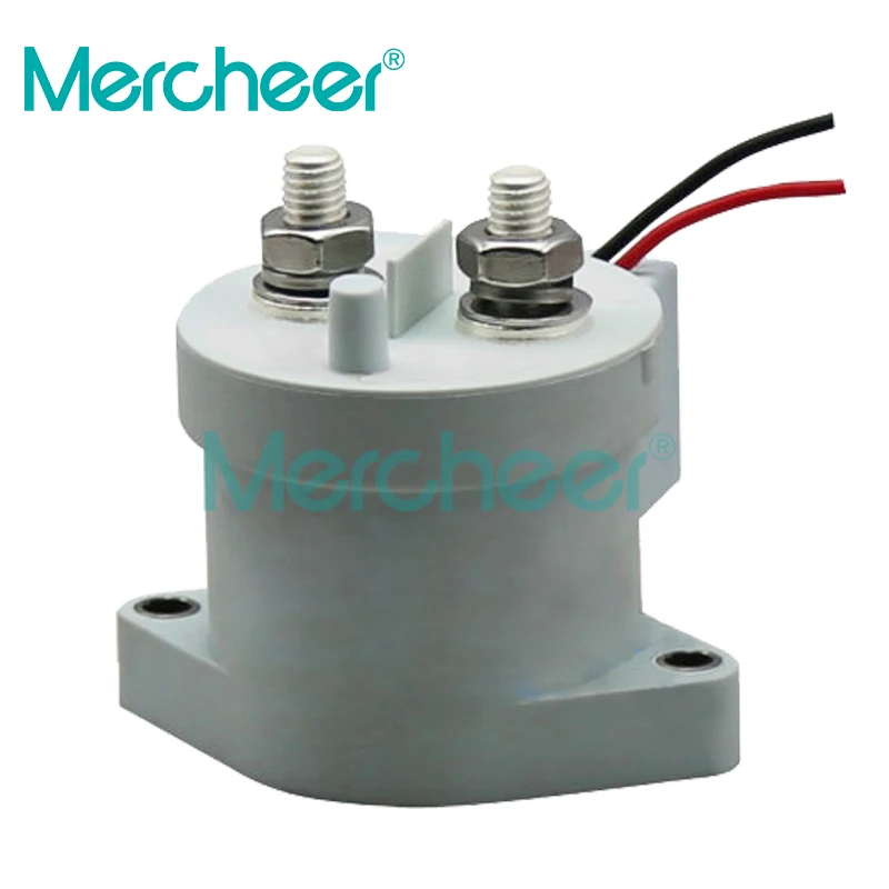
I wouldn't recommend that style or model of contactor. I've heard too many bad things about those. I would look for a Gigavac ora TE/Sensata Kilovac. 100A is still good. I personally use 400A models from DC-Contactor.com.
This one specifically.
I order factory direct but they maybe have them on aliexpress?
Here is one I found on a quick look:
Smarter Shopping, Better Living! Aliexpress.com

www.aliexpress.com
Not the same brand and it's 500A. But that store looks like they may have others.