Ozark Tinkering
Solar Addict
- Joined
- Dec 23, 2021
- Messages
- 1,109
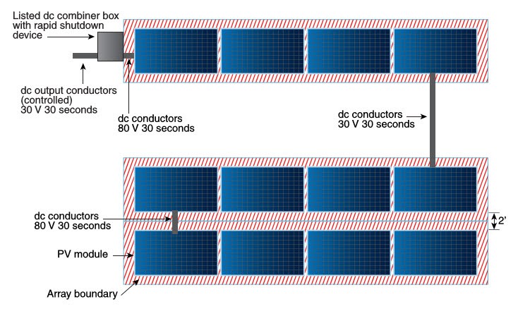
Recently there's been a lot of talk around grounding and neutral issues on some of these AIOs coming from China without any UL testing. Here's a start to the conversation that I think any DIYer needs to pay very close attention to prior to embarking on a build that attempts to act as their separate source of power. It applies to ALL systems regardless of manufacturer. This is for US installations but likely has would apply anywhere based on best practice imho. Near the front of the NEC is Art. 100 and NEC Art. 100 defines a Separately Derived System as “An electrical source, other than a service, having no direct connection(s) to circuit conductors of any other electrical source other than those established by grounding and bonding connections.”
That describes most of us.
Grounding separately derived systems
Grounding
By Jack Smith
As I promised in my last column, this "Solid Ground" column deals with transformers and grounding. Let's start by addressing some definitions. Opinions differ on the "official" definition of "distribution" transformer. However, the U.S. Federal Register (Vol. 71, No. 81; page 24,995, issued April 27, 2006) defines a distribution transformer as one that meets all of the following criteria:
Although vague, this definition seems to imply that a distribution transformer is typically a utility-owned unit usually found at a substation or the utility side of a service. Many of us recall labeling these as power transformers. Apparently, the current widely accepted usage is that a distribution transformer serves a utility customer, while a power transformer serves an area.
Service conductors - according to the NEC - originate at the utility service point and terminate on the line side of the service equipment. Conductors and equipment on the load side of the service equipment - such as secondary conductors from customer-owned transformers; conductors from generators, UPS systems, or photovoltaic (PV) systems; and conductors serving remote structures - are considered feeder conductors.
A separately derived system is "a premises wiring system whose power is derived from a source of electric energy or equipment other than a service. Such systems have no direct electrical connection, including a solidly connected grounded circuit conductor, to supply conductors originating in another system," according to the NEC. Examples of a separately derived system include transformers in which the supply, or primary, is isolated from the secondary except by magnetic coupling; generators (stand-alone or alternate power source) where the grounded conductor (neutral) is not solidly connected in the transfer switch; battery/inverter systems where the output is not interconnected; and off-grid PV systems.
Proper transformer grounding is critical. Making a grounding connection - typically to building steel, which is required to be bonded to all cold-water pipes - establishes a ground reference. Make proper bonding connections by exothermic weld, not clamps that can loosen over time. Ensure that the high-frequency impedance of the grounding electrode conductor is as low as possible. Wide, flat conductors have less inductive reactance at higher frequencies, and are preferred to round conductors for that reason. The distance between the neutral-ground (N-G) bond at the transformer and the grounding electrode should be as short as possible.
The neutral and ground must be connected to the transformer neutral bus. Making the N-G bond at the main panel is not advised in order to segregate normal return currents from ground currents. The transformer neutral bus is the only point on the system where the neutral and ground should be bonded.
Separate "isolated" ground rods are notorious for creating two ground references at different potentials. This situation causes ground-loop current to circulate to attempt to equalize this difference in potential. This situation can cause intermittent system and equipment problems as well as a potential safety and equipment hazard.
Transformer ground inspection should be part of your maintenance routine. Here are some suggestions of things to look for when inspecting transformer grounds:
That describes most of us.
Grounding separately derived systems
Grounding
By Jack Smith
As I promised in my last column, this "Solid Ground" column deals with transformers and grounding. Let's start by addressing some definitions. Opinions differ on the "official" definition of "distribution" transformer. However, the U.S. Federal Register (Vol. 71, No. 81; page 24,995, issued April 27, 2006) defines a distribution transformer as one that meets all of the following criteria:
- Has an input voltage of 34.5 kV or less
- Has an output voltage of 600 V or less
- Is rated for operation at a frequency of 60 Hz
- Has a capacity either of 10 kVA to 2500 kVA for liquid-immersed transformers or 15 kVA to 2500 kVA for dry- type transformers.
Although vague, this definition seems to imply that a distribution transformer is typically a utility-owned unit usually found at a substation or the utility side of a service. Many of us recall labeling these as power transformers. Apparently, the current widely accepted usage is that a distribution transformer serves a utility customer, while a power transformer serves an area.
Service entrance
According to the National Electric Code (NEC), Article 100, the service entrance is the single point at which electrical power enters a facility. Service equipment usually includes circuit breakers, switches, fuses, and their accessories, and connects to the load end of the service conductors. The service equipment is the main control and electrical supply cutoff, but does not include metering equipment.Service conductors - according to the NEC - originate at the utility service point and terminate on the line side of the service equipment. Conductors and equipment on the load side of the service equipment - such as secondary conductors from customer-owned transformers; conductors from generators, UPS systems, or photovoltaic (PV) systems; and conductors serving remote structures - are considered feeder conductors.
A separately derived system is "a premises wiring system whose power is derived from a source of electric energy or equipment other than a service. Such systems have no direct electrical connection, including a solidly connected grounded circuit conductor, to supply conductors originating in another system," according to the NEC. Examples of a separately derived system include transformers in which the supply, or primary, is isolated from the secondary except by magnetic coupling; generators (stand-alone or alternate power source) where the grounded conductor (neutral) is not solidly connected in the transfer switch; battery/inverter systems where the output is not interconnected; and off-grid PV systems.
Grounding and bonding
Grounding means connecting something to the earth. Bonding means connecting objects together. A separately derived system must be grounded to earth at the source. All non-current-carrying metal parts and equipment must be bonded to the grounding point of the derived system. Bonding of metal equipment provides an effective ground-fault current path to ensure that the electrical system is safe from the potential for electric shock and fires. Proper grounding of separately derived systems stabilizes phase-to-ground voltage. NEC Article 250 in general and 250-26 in particular address the grounding requirements of a separately derived system.Proper transformer grounding is critical. Making a grounding connection - typically to building steel, which is required to be bonded to all cold-water pipes - establishes a ground reference. Make proper bonding connections by exothermic weld, not clamps that can loosen over time. Ensure that the high-frequency impedance of the grounding electrode conductor is as low as possible. Wide, flat conductors have less inductive reactance at higher frequencies, and are preferred to round conductors for that reason. The distance between the neutral-ground (N-G) bond at the transformer and the grounding electrode should be as short as possible.
The neutral and ground must be connected to the transformer neutral bus. Making the N-G bond at the main panel is not advised in order to segregate normal return currents from ground currents. The transformer neutral bus is the only point on the system where the neutral and ground should be bonded.
Looking for trouble
Excessive ground current and ground loops can cause equipment malfunction, inaccurate instrument readings, and safety issues. Two sources for excessive ground current are illegal N-G bonds, which can show up in subpanels, receptacles, or equipment; and "isolated" ground rods. Subpanel N-G bonds create a parallel current path by allowing normal return current to return through the grounding conductor. This creates a situation where the equipment safety ground would become the only return path if the neutral ever becomes open. Dangerous voltages could develop if the return path is high impedance.Separate "isolated" ground rods are notorious for creating two ground references at different potentials. This situation causes ground-loop current to circulate to attempt to equalize this difference in potential. This situation can cause intermittent system and equipment problems as well as a potential safety and equipment hazard.
Transformer ground inspection should be part of your maintenance routine. Here are some suggestions of things to look for when inspecting transformer grounds:
- Check the integrity of the N-G bond using a high-quality ground impedance tester - a high-impedance N-G bond can cause voltage fluctuations
- Check the integrity of the grounding conductor and its connection to building steel using a high-quality ground impedance tester - fault currents return to the source through these connections; their impedance should be as low as possible
- Measure for ground current on the grounding conductor using a high-quality clamp meter - anything above 1 A should be cause for suspicion.

Last edited:
")