diy solar

diy solar

don't understand Lifepo charging, seems like voltage/time-based charging is flawed?

blutow

Solar Enthusiast
Joined
Dec 20, 2020
Messages
344
I'm in the process of designing a solar system for a van and it will include lifepo batteries and 3 charge sources (solar, alternator, inverter/charger).

I'm going with victron equipment and trying to educate myself on how to configure the various charging sources to best charge the batteries to ensure maximum service life. They all seem to be using "traditional" phases of bulk, absorption, and float based on voltage and time.

With lifepo voltage being so flat across the bulk of it's SOC, I don't understand how these charging sources can optimize the charging cycle when voltage isn't a great indicator for SOC. For example, how does the inverter know when the solar is also making big contributions to charging so that it reduces the duration of bulk or absorption? Shouldn't those stages be shorter if more amps are being pushed from multiple sources? I assume battery voltage will drive adjustment at the extremes, but that doesn't seem great with the the flat voltage curge on lifepo. If the charger isn't constantly looking at net charge on the battery across all charge sources (and considering loads as well), I don't see how it could know how long to apply charge at a given voltage. As an example, I might have the inverter charger configured for 1 hour of absorbtion time, pushing 50 amps to the batteries. Does that 1 hour get adjusted down when solar is pushing another 50 amps at the same time? Does it get adjusted longer when there is 95amps of load offsetting most of the charging (so really only charging 5 amps "net)?

Assuming you have an accurate shunt on the system, wouldn't the % state of charge for the battery be a key input to how charging volts and amps should be optimized? I'm not saying the system should ignore voltage completely, but it just seems like SOC woudl be a better "primary" driver to optimize the chargers for the bulk of the charge cycle. It seems like it woudl be pretty simple to allow the shunt to determine state of charge and all the charging sources could adjust voltage/current accordingly with some sanity checks for battery voltage to override when neccessary.

All that said, I'm pretty new to this stuff and just designing my first system now. I'm probably overthinking this, but everything I read about lifepo and charging gets me confused, expecially when I see fixed timeframes defined for the various charge phases regardless of number of sources. Is my line of thinkikng flawed? Is there something happening in these systems I'm not considering? Just trying to get educated on this stuff the best I can at this point.
 
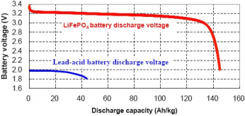
One thing to remember: bulk/absorption/float etc. are coming from the lead-acid world and are pretty meaningless in the world of LiFePO4. There is no optimization of the charge cycle: you throw power at it and the cells absorb the power, across the entire cycle from empty to full. This simplifies things a lot: the inverter will take whatever it needs, and if there is more, it goes to the battery. If the battery can take the power, and it's there, it will take it. The end. If the battery is full, it sits at the upper knee and the charging stops. If the battery is empty, it goes in the lower knee and the BMS will cut off (or the inverter if you will) because the voltage is too low. In between those, it doesn't matter - as long as you don't 'float' the battery at high state of charge by keeping the charge voltage when the battery is full - that's why the float voltage is usually configured to something like 3.4V or less per cell (well below what you would on lead acid)

Edit, and to clarify:
everything I read about lifepo and charging gets me confused, expecially when I see fixed timeframes defined for the various charge phases regardless of number of sources.
If you take a 280Ah LiFePO4 battery at 50% SoC and you have an MPPT that can dump 35A at it, it will charge to 100% (simplified) in 4 hours. If you add an MPPT to double that, it will do in 2 hours. There are no stages.
 
Last edited:
One thing to remember: bulk/absorption/float etc. are coming from the lead-acid world and are pretty meaningless in the world of LiFePO4. There is no optimization of the charge cycle: you throw power at it and the cells absorb the power, across the entire cycle from empty to full. This simplifies things a lot: the inverter will take whatever it needs, and if there is more, it goes to the battery. If the battery can take the power, and it's there, it will take it. The end. If the battery is full, it sits at the upper knee and the charging stops. If the battery is empty, it goes in the lower knee and the BMS will cut off (or the inverter if you will) because the voltage is too low. In between those, it doesn't matter - as long as you don't 'float' the battery at high state of charge by keeping the charge voltage when the battery is full - that's why the float voltage is usually configured to something like 3.4V or less per cell (well below what you would on lead acid)

Edit, and to clarify:

If you take a 280Ah LiFePO4 battery at 50% SoC and you have an MPPT that can dump 35A at it, it will charge to 100% (simplified) in 4 hours. If you add an MPPT to double that, it will do in 2 hours. There are no stages.

I get the simplified amps in and out, but struggling the time and volts. I've seen "absorbtion" recommendations of 14.4 for multiple hours. I assume that could make sense if the multiplus charger was the only source, but what if I had 3 charger sources all pushing that at the same time for multiple hours? Isn't it potentially unhealthy to hold at this kind of voltage for a "fixed" extened period? The timeframe just seems somewhat arbitrary it's it's not considering total amps being pushed across all charge sources (as well as considering what other loads might be ofsetting the charging current).
 
lifepo4 has a far "flatter curve". which means the voltage difference between 15% or 80% charged is very little. most of readers that will tell you the % of battery on a lithium will either "learn it" or guesstimate based on how much it charged/discharged it 1609700026299.png
 
lifepo4 has a far "flatter curve". which means the voltage difference between 15% or 80% charged is very little. most of readers that will tell you the % of battery on a lithium will either "learn it" or guesstimate based on how much it charged/discharged it View attachment 32063
I guess that's my point. Trying to throttle charging voltage and amps based on battery bank voltage (with such a flat curve) seems like a bit of a shot in the dark with all the moving pieces. If my shunt is measuring amps in and out, it will quickly have a pretty good idea what the current % state of charge the battery is in. So why not design a system that throttles charging voltage based on soc % and just use bank voltage as a secondary input (sanity check)? It seems like you'd just want to dump up to .5C into the bank at fairly high voltage until you are hitting ~90% SOC (or whatever point makes sense) and then throttle back from there rather than trying to guess with voltage and an arbitrary absorption time.
 
but what if I had 3 charger sources all pushing that at the same time for multiple hours?

You would charge faster and end up faster at the upper knee where you would stop charging.

Isn't it potentially unhealthy to hold at this kind of voltage for a "fixed" extened period?

If you have a 10 chargers and they all charge the same battery, the time until you reach the upper knee decreases and you don't hod that voltage for a long time. As I mentioned, when you apply a charger, or multiple chargers, the battery will take the energy until it can no longer and go to 3.65V where you stop charging (and don't keep a voltage).
 
It's far easier to estimate State Of Charge from voltage and current while charging.
Battle Born specifies LiFePO4 settings for Victron.
 
You would charge faster and end up faster at the upper knee where you would stop charging.


If you have a 10 chargers and they all charge the same battery, the time until you reach the upper knee decreases and you don't hod that voltage for a long time. As I mentioned, when you apply a charger, or multiple chargers, the battery will take the energy until it can no longer and go to 3.65V where you stop charging (and don't keep a voltage).
Yeah, I get that you aren't going to totally destroy your cells and exceed the absolute voltage limits of the cells, but I'm hoping to design a system that charges conservatively and would never hit 3.65/14.6. I plan to set my BMS at those limits, but I hope my BMS is just a safety blanket and my charging sources can be configured to set more reasonable limits. Why push into 3.6-3.65 territory when you can get to ~90% capacity just staying on the flat part of the curve? Again, I'm no expert, but everyting I've read is that lifepo will last longer (particularly in the heat) if you don't make a habit of toping it off all the time. It just seems like a challenge to figure out the 90% stopping point if you are going off voltage rather than capacity.
 
It's far easier to estimate State Of Charge from voltage and current while charging.
Battle Born specifies LiFePO4 settings for Victron.
Agree that it's easy to estimate SOC, but I don't think a single charging source can do that on it's own. That's why I'm asking whether all charging souces could consider SOC (simple calculation from a single shunt for the entire system) as an input for how to charge.

Battleborn does provide recommendations and that is part of my source of confusion. How can they recommend x hours of absorption per 100ah battery at 14.? volts for a single charge source without knowing what the active load is on the system and what other charging sources might be contributing?
 
Why push into 3.6-3.65 territory when you can get to ~90% capacity just staying on the flat part of the curve?
Oh absolutely, you can set this lower (I tend not to go over 3.5), but this is still more than enough margin on the voltage fro the MPPT to stop charging. 3.5V in a '12V' configuration is 14V; most MPPT chargers I've seen allow at least .1V accuracy.

Have a look here as well:
 
Agree that it's easy to estimate SOC, but I don't think a single charging source can do that on it's own. That's why I'm asking whether all charging souces could consider SOC (simple calculation from a single shunt for the entire system) as an input for how to charge.

Battleborn does provide recommendations and that is part of my source of confusion. How can they recommend x hours of absorption per 100ah battery at 14.? volts for a single charge source without knowing what the active load is on the system and what other charging sources might be contributing?
That's why I bought a Victron Smart Shunt ($130) to go with the Victron Smart Solar Charge Controller. It can supply battery voltage and current data to the smart solar controller(s). Smart Shunt a thin fused lead to connect to battery +. Best voltage accuracy would require low resistance between shunt and battery -. Yea it's pricey, but so are LiFePO4, and I have the extra bucks.
 
That's why I bought a Victron Smart Shunt ($130) to go with the Victron Smart Solar Charge Controller. It can supply battery voltage and current data to the smart solar controller(s). Smart Shunt a thin fused lead to connect to battery +. Best voltage accuracy would require low resistance between shunt and battery -. Yea it's pricey, but so are LiFePO4, and I have the extra bucks.
Yep, I've got one of those on the way along with my other victron components. Are you saying the solar charger is able to look at something besides battery voltage to figure out how to charge? I haven't really dug into the solar charger yet. I didn't see settings on the multiplus that supported much beyond voltage and temp, but some of their documentation is a little disjointed.

I think I'd like to be able to set the system to stop charging at ~90% (even if battery voltage hasn't hit the steep ramp yet ). You could still have a fallback to stop charging at ~14.3V in case your SOC is out a whack with the shunt/monitor. So, the logic would be to stop charging at 90% SOC or 14.3V (at the battery), which ever comes first.
I believe that at 14.3V with 14.3V setting the current will drop off, and it will go float. There is a Tail Current setting to exit absorption. (for lead acid only???). Don't have my LiFePO4 batteries yet.
 
Yep, I've got one of those on the way along with my other victron components. Are you saying the solar charger is able to look at something besides battery voltage to figure out how to charge? I haven't really dug into the solar charger yet. I didn't see settings on the multiplus that supported much beyond voltage and temp, but some of their documentation is a little disjointed.

I think I'd like to be able to set the system to stop charging at ~90% (even if battery voltage hasn't hit the steep ramp yet ). You could still have a fallback to stop charging at ~14.3V in case your SOC is out a whack with the shunt/monitor. So, the logic would be to stop charging at 90% SOC or 14.3V (at the battery), which ever comes first.
If you get a BMV-712 instead of the Smart Shunt, they BMV-712 will control the MPPT Smart Solar via Blue Tooth (no wiring required).

I recommend the BMV-712 over the Smart Shunt also because it has a relay output that can be used to control all of your charge sources Orion-TR (alternator charger), Multiplus (inverter/charger). I have a temperature sensor on my BMV-712, and it stops all charging any time the battery temperature drops below -5 degrees C.
I decided to do the Cerbo GX with the touch 50 screen and I didn't want the extra screen that came with the 712. The cerbo has a couple relays and multiple inputs for temp and tank levels and also some digital inputs (which I doubt I'll ever use). It can connect to the inverter and solar charger, but I don't think it really talks with the the Orion (but could turn it on/off via relay I guess). I will leverage the temp sensors to suppress charging for sure and to trigger heating pads on batteries and water tank. When you say the 712 can control your charge sources, are you saying it can turn them on or off or is there something more to it than that?
 
You are overthinking things. Set your primary charge controller to 3.45V, set all other charge controllers to 3.4V.

I often go for months without my cells going over 80% SOC. I am yet to find anything that can accurately measure SOC when it isn’t regularly “reset”

If you set your Victron BMV to read 100% when your battery is at 90%, then expect to be able to consistently hit this mark as a maximum SOC over the years, you will be disappointed.
 
You are overthinking things.

Most certainly, I'm just trying to understand this stuff better and I find it interesting. It just seems odd to me that with all the processing power and communication between devices in these modern systems, the charge settings are still set at the individual charger level @ X volts for y hours with minimal consideration of system load or what the other charging devices are doing.

I get that the voltage monitoring keeps everything in check and needs to be a key consideration, but it seems like these interconnected systems would be smarter. I understand that determining SOC is not a layup if you aren't regularly hitting the upper and lower limits of the system regularly, but it still seems like it could be a valuable input. Even if it only makes sense to look at voltage to dictate charging behavior, it still seems like it would be better for all the chargers to be coordinated by a single centralized "brain" that is looking at voltage at the battery bank and then gets all the chargers "rowing together".

I'm sure part of this is that I have some background in IT with complex systems that leverage machine learning and analytics, so my my brain is wired to think a system should take in all the relevant data and optimize decisions based on that. It sounds like may be there is little or no value to doing anything smarter than x volts for y hours at the individual charger level, but that is really at the heart of what I was trying to figure out.
Take a close look at Victron. Beyond the feel good 4 color pdf. Their main market are professional installers, and they have training.
Smart Networking , panels and system , Xscapers boondocking stage trailer
 
Take a close look at Victron. Beyond the feel good 4 color pdf. Their main market are professional installers, and they have training.
Smart Networking , panels and system , Xscapers boondocking stage trailer
thanks, that is good stuff. It looks like there is support to sync up charging behavior across multiple solar chargers. It's not supported yet for Orion B2B (but looks like it is planned) and I don't see any mention of multiplus charging sync. If they have already started down this path, eventually I expect you'll be able to sync all charge sources (at least all Victron charge sources). It allows you to optimize charging output and arguably simplifies the system. You could have one master device that controls all the others. Maybe the cerbo can already do some of this or maybe that's a future plan for Victron. It seems like the current approach is to use one of the chargers as a master and then all the others fall in line. The more you can centralize the brain, the less you need to have chargers with lots of smarts doing things in a vacuum. Rather than complicating and adding cost to every charger, you could make the brain really smart and look across the entire system to coordinate charging. The individual chargers should be smart enough to optimize power gathering from their sources, but could let a master device figure out how to apply the charge to the battery bank in a coordinated effort.
 
If you want simple, use the SMA system.

DC / AC / Generator (and mains grid if required) can all be controlled by your LiFePO4 BMS (Batrium / REC / Zeva)

Your original question was why SOC wasn’t used as the primary charger control parameter. The answer is that it is an unreliable indicator. All SOC monitors rely on voltage setpoints and charge current to determine the SOC, and as the charge/discharge efficiency of the battery varies - the SOC needs to be reset.

To put it simply, SOC is a measure of amps in and out of the battery.

One day 100 amps out plus 105 amps in will return to 100%SOC

The next day 100amps out plus 110 amps in will return to 100%SOC

The SOC meter will use a preset voltage/current setpoint and reset to maintain an acceptable level of accuracy.

For charging your batteries, it makes more sense to directly use the voltage/current setpoint.

For charging only, there is no need for central control of multiple charge sources. Control is only needed for balancing - and that is a whole other discussion.
 
Back
Top