FilterGuy
Solar Engineering Consultant - EG4 and Consumers
I agree. I still think the burning wire was a secondary effect due to improper fusing. If a bad connection caused a heat problem that created a short. I would have expected it to take long enough to heat up most of the wire. Also, the reported load on the inverter at the time of the failure was very low....This means that while it was working the inverter was not drawing a lot of current so any heating would have been slow and would have traveled down the wires..For a fast fault (1s<t<10s) I have seen one end of a 2' cable be hot and the other just warm. It usually depends on which side of the cable termination was the source of heat.
I wish I knew what the circuit in the upper left of the unit was. Was it's failure also a secondary effect or was it the primary failure that cascaded.
My SWAG remains this:
1) Something in the Inverter failed and caused a low resistance short (If the FETs shorted it could cause this).
2) The short created a sudden high surge in current. Even with the 100A Fuses, the current could have been well north of 200A total.
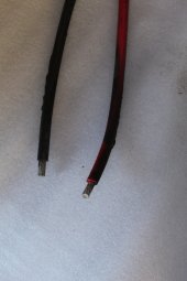
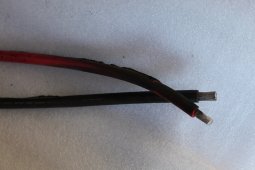
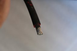
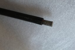
3) A bad connection or a bad crimp on 4AWG battery wires was the hottest part of the circuit and caused the fire.
Question: Can we get a picture of where the cables are connected to the inverter? Is there any indication the heat came from or went into the inverter itself?
As far as what caused the initial problem that cascaded into the fire.... we have so little information that anything said is speculation.... but what the heck... I'll speculate.
The OP states that the charging seemed to have stopped just prior to the failure
The OP states he had north of 400V on the PV input..... And the 500V design is brand new on the EG4 versions of these inverters. (Could there be a design flaw?)
Could something have fried on the Charge controller? It has a direct connection to the batteries so a short in the charge controller could create a huge current on the battery input. (Could the burnt circuit in the upper left be the solar charge controller?)