diy solar

diy solar

EG4 6.5kW Off-Grid Inverter cable size? Signature Solar

LBART

New Member
Joined
Mar 4, 2023
Messages
44
Location
Wisconsin
I haven't found a clear thread on this or my search ability is a bit lacking.

In contacting the design team at Signature Solar I was planning on purchasing the EG4 6.5kW Off-Grid Inverter, with 2 EG4-LL Lithium Battery (V2) | 48V 100AH and the Nader DC Circuit Breaker | 60V 200Amp. The quote had the 84in 1 AWG Battery to Inverter Cables | Black and Red which I also see on the set of 2 6500's.

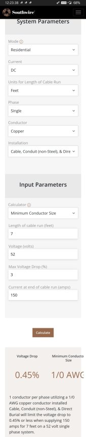
I am concerned that the 1AWG is too small. In the manual on page 12 it states
Typical Amperage 153A
Minimum Wire Size >1/0AWG or greater than.
I did call but can't reach the design team via the phone so I spoke with support and he said 2/0AWG is the minimum he recommends.
So why does Signature Solar quote and include in their sets 1AWG which is below the recommended spec? And would it be fine to accept that? This is my only concern before making the purchase. I did email the one from the design team I was working with but either she is off for a few days or doesn't want to answer my email.
 
Can’t say why they quoted a 1awg, but I’ve also heard (and used) a 2/0 from the battery to each inverter. Better safe than sorry.
 
Can’t say why they quoted a 1awg, but I’ve also heard (and used) a 2/0 from the battery to each inverter. Better safe than sorry.
I know why they did see the links. I just don't understand specing it out below the manual's specs.

This one shows the 1AWG as an accessory.


On the bundle
Bundle Contains:

2 x EG4 6500ex-48 6.5kW Off-Grid Inverters
2 x 200A Nader Breakers
2 x IMO DC Disconnect Rooftop Isolator Switch
2 x 84in 1 AWG Battery to Inverter Cables | Black and Red
 
the minimum specced is 2awg, we went 1 size up at the short length of cables we include

the manual is always showing higher than needed as we cannot trust that the run doesn't get extended beyond 15ft
 
It looks like the design team is using the ampacity tables for conductors in free air. Most if not all installations don't fit the NEC definition of conductors in free air. Go with 2/0 copper. Yes it is more expensive but you won't need that much.
 
It looks like the design team is using the ampacity tables for conductors in free air. Most if not all installations don't fit the NEC definition of conductors in free air. Go with 2/0 copper. Yes it is more expensive but you won't need that much.
We use in conduit figures sir.
 
It looks like the design team is using the ampacity tables for conductors in free air. Most if not all installations don't fit the NEC definition of conductors in free air. Go with 2/0 copper. Yes it is more expensive but you won't need that much.
any more than 15 ft you are right
 
The nameplate on the unit shows DC input to be 153.8A, not 137. Your voltage drop calculator is set up for three phase power, not DC. It isn't just about voltage drop, although that directly relates to the power dissipated in the wire and hence its temperature rise.

Bottom line, these conductors need to be sized for 153.8*1.25 or 192A. #1 in conduit doesn't come close to meeting code, even using 90C wire. 90C is in itself a stretch, the DC input terminals aren't rated for 90C - nowhere in the manual is it stated they are 90C - so you can't base the wire ampacity on that temperature.
they are 200C as per UL electronics

please review the shot, it was set to DC sir

the inverter can take down to 40v, hence the higher amps max (not relevant to LFP 16S packs)

the cables we sell are 105C

If you can show with ohms cals, NEC calcs (on accurate data) or a thermal gun then by all means safety first.
10 years back I was the kid that $50 meant a lot to; we do not want to pile on the cost that does not make the system safer anyway. Everyone here is free to use 4/0 if they want and have the extra money lying around.
 
BTW, the manual recommends a minimum of 1/0.

$50 is cheap insurance when compared to the damage resulting from an electrical fire.

I'm not trying to be a d*ck, but your opinion concerning what "does not make a system safer anyway" is not congruent with national codes.
 
Also, the shot clearly states the above calculations are based on conductor impedance in a theee phase system. Maybe just an error when DC is selected, I don't know.

Insurance adjusters, inspectors, etc don't care what anyone "considers safe". In the end, prescriptive codes control this and my opinion is that #1 wire is not allowed in this application. It may well be safe, but it is not allowed.

We will just have to agree to disagree, but it is not my professional insurance that will have to cover it, thankfully!
 
BTW, the manual recommends a minimum of 1/0.

$50 is cheap insurance when compared to the damage resulting from an electrical fire.

I'm not trying to be a d*ck, but your opinion concerning what "does not make a system safer anyway" is not congruent with national codes.
My calc is set to NEC
Already explained the 1/0 in the manual as people can fudge the lengths, could have put a table with different gauges per length tho. the EE's that built it recommended 2AWG minimum in their spec. I don't say 2awg because we'll end up with 30ft runs of 2 gauge

Also, the shot clearly states the above calculations are based on conductor impedance in a theee phase system. Maybe just an error when DC is selected, I don't know.

Insurance adjusters, inspectors, etc don't care what anyone "considers safe". In the end, prescriptive codes control this and my opinion is that #1 wire is not allowed in this application. It may well be safe, but it is not allowed.

We will just have to agree to disagree, but it is not my professional insurance that will have to cover it, thankfully!

The selection is DC. run any other calc if you want with the parameters mentioned and see the same results

If an NEC calc and the UL successful manufacturer spec "isn't allowed" then is there some kind of secret book I need to read? please show proof of work if you want to close by labeling it "unsafe"
 
Last edited:
It would be nice to find an official chart based on voltages amperage and lengths. During my searching it was all over the place. An NEC or UL approved chart would be best then it could be added to the resources here.
 
My calc is set to NEC
Already explained the 1/0 in the manual as people can fudge the lengths, could have put a table with different gauges per length tho. the EE's that built it recommended 2AWG minimum in their spec. I don't say 2awg because we'll end up with 30ft runs of 2 gauge


The selection is DC. run any other calc if you want with the parameters mentioned and see the same results

If an NEC calc and the UL successful manufacturer spec "isn't allowed" then is there some kind of secret book I need to read? please show proof of work if you want to close by labeling it "unsafe"
Educate me please... The calculator i used agrees with the manual.


Ps - I'm using 1awg ul listed marine cable in my build and things are just fine but runs aren't very long, under 10'.


Attachments

  • Screenshot_20230402-002351.jpg
    Screenshot_20230402-002351.jpg
    33.1 KB · Views: 6
Back
Top