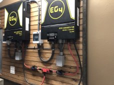
Setup is 2 - EG4 6500 ex inverters
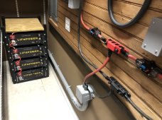
4 - EG4 LiFePower battery’s
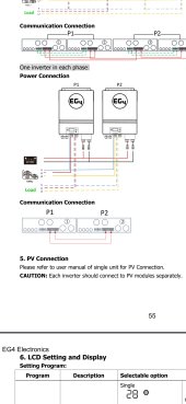
I was wanting to run this system in split phase configuration, but I discovered some issues along the way.
First - When making the battery selection in the inverter menu #5 I could not choose the EG4 battery setting because a fault #61 would constantly flash saying comm loss with the battery. All comm cable connections were hooked up per manual. The only way to stop the alarm was to select battery type as user and input my own battery voltage settings. I really don’t care for all the communication cables, can I run without them and allow the inverter to know battery status just by old school voltage??
Second - When placing both inverters to the split phase connection, I identified one as 2P1 and the other as 2P2. After this setting had been made, I shut down both inverters and performed a restart. Upon restart, both inverters turned on, 2P1 only shows the battery icon, 2P2 shows the battery icon, A/C to D/C icon and Power output icon. Since 2P1 only shows battery icon it auto shuts down within about 20 seconds. Also with 2P1, it displays 2P1 in the top left hand corner along with the battery icon in the center. 2P2 doesn’t display its setting on the LCD screen in the top left hand corner. What’s going on? I would like to run these split phase to run my well.
Lastly - if both of these inverters get setup to run in the split phase configuration, can I only run a single string of solar panels
(120v@10 amps) to only one inverter to charge the batteries? Or do I have to balance solar inputs between inverters?
This system is only off grid.
4 - EG4 LiFePower battery’s
I was wanting to run this system in split phase configuration, but I discovered some issues along the way.
First - When making the battery selection in the inverter menu #5 I could not choose the EG4 battery setting because a fault #61 would constantly flash saying comm loss with the battery. All comm cable connections were hooked up per manual. The only way to stop the alarm was to select battery type as user and input my own battery voltage settings. I really don’t care for all the communication cables, can I run without them and allow the inverter to know battery status just by old school voltage??
Second - When placing both inverters to the split phase connection, I identified one as 2P1 and the other as 2P2. After this setting had been made, I shut down both inverters and performed a restart. Upon restart, both inverters turned on, 2P1 only shows the battery icon, 2P2 shows the battery icon, A/C to D/C icon and Power output icon. Since 2P1 only shows battery icon it auto shuts down within about 20 seconds. Also with 2P1, it displays 2P1 in the top left hand corner along with the battery icon in the center. 2P2 doesn’t display its setting on the LCD screen in the top left hand corner. What’s going on? I would like to run these split phase to run my well.
Lastly - if both of these inverters get setup to run in the split phase configuration, can I only run a single string of solar panels
(120v@10 amps) to only one inverter to charge the batteries? Or do I have to balance solar inputs between inverters?
This system is only off grid.