diy solar

diy solar

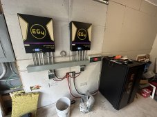
EG4 6500ex's finally wired up.

RGH69

New Member
Joined
Sep 4, 2022
Messages
115
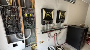
I wired up the EG4 6500's that are replacing the LV6548's that I kept having issues with. I made a video for y'all to look at and see if you think that I should do something else before firing them up. I'm a little start-up shy since I had so many issues with the LV6548's.
Thumbnail EG4.JPG

I changed the way I had everything wired with the LV6548's. I went with the wiring trough and conduit like Adam DeLay's setup.


Here is the video...
 
Okay, It is up and running. Had to update the firmware on one because of the error 61. But I got it all running now. Starts off of Battery, Grid input works, Output current works fine on the critical loads panel and the PV input works. The system is running in bypass now but will test changing to SUB tomorrow.

photo_2023-03-13_19-17-37.jpg
 
Looks good. Did you end up going with the 4" wire trough?

I like the little yellow labels you have on each wire.
 
Yes 4x4. However, I recommend 6x6 if you plan to use #4 wire so you don't have to make such a tight bend when running the wire up the conduits. The yellow labels are printed heat shrink tubing from a Dymo 4200 label maker.
 
Yes 4x4. However, I recommend 6x6 if you plan to use #4 wire so you don't have to make such a tight bend when running the wire up the conduits. The yellow labels are printed heat shrink tubing from a Dymo 4200 label maker.
I've heard a lot of recommendations to just go big and get the 10x10. I know there's a cost difference, but after seeing what it looks like with all the wires crammed in there, might not be a bad idea.
 
I've heard a lot of recommendations to just go big and get the 10x10. I know there's a cost difference, but after seeing what it looks like with all the wires crammed in there, might not be a bad idea.
Mine is 8x8 and I couldn't get the Victron 1000A busbar inside it. Purchased what I could find off ebay on the cheap.
 
I wired up the EG4 6500's that are replacing the LV6548's that I kept having issues with. I made a video for y'all to look at and see if you think that I should do something else before firing them up. I'm a little start-up shy since I had so many issues with the LV6548's.

View attachment 139337

I changed the way I had everything wired with the LV6548's. I went with the wiring trough and conduit like Adam DeLay's setup.


Here is the video...
Explain the Polaris connector connections. I have one on the neutral from each inverter to combine the neutrals. From watching the video, it almost appears to be one on the L1 and L2?
 
Explain the Polaris connector connections. I have one on the neutral from each inverter to combine the neutrals. From watching the video, it almost appears to be one on the L1 and L2?
From what I saw in the video, it looks like he had one 3-way polaris connector for his neutral but then 2-way connectors for his L1 and L2 to extend his cables.

I actually did a double take for a second because I thought he was splitting his L1 and L2 off the same wire just from the way some of the discussion was and what I saw in the trough. He's not. It was the neutral I was seeing.
 
Explain the Polaris connector connections. I have one on the neutral from each inverter to combine the neutrals. From watching the video, it almost appears to be one on the L1 and L2?
I did the polaris on the input grounds and neutrals. I also did a polaris on L1 because the wire was short and I didn't want to pull new cable through the wall.
 
  • Like
Reactions: Zwy
From what I saw in the video, it looks like he had one 3-way polaris connector for his neutral but then 2-way connectors for his L1 and L2 to extend his cables.

I actually did a double take for a second because I thought he was splitting his L1 and L2 off the same wire just from the way some of the discussion was and what I saw in the trough. He's not. It was the neutral I was seeing.
Correct! Good eyes!
 
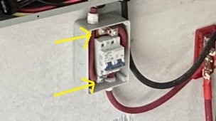
I used the box below. But you have to unscrew the aluminum lugs and mount them sideways. like this.
I’m thinking of getting these Jboxes. I just posted a comment on your YouTube channel. I just want to make sure it will fit the wire gauge I’m using or at least know what fits so I can make changes in needed.

Did you run 4/0 from the battery bank to your bus bars and then run 2/0 from the bus bars to the disconnect and then the inverters?

I want to make sure the glands that come with that Jbox (HT-5 way) will work with 2/0.

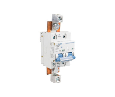
I think I have the same disconnects as you, the

Nader DC Circuit Breaker | 60V 200Amp​

 
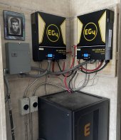
Here is my setup now. As you can see, I’m pretty tight on space. Putting the Nader breakers in a Jbox will limit me even more. Waiting to hear back from the electrical inspector to see if the busbars also have to go in a Jbox.


64D17056-F308-44D3-81F0-50F506F24377.jpeg

D6788A2F-E6F6-4373-9B88-EC7DB7E44541.jpeg


If the bus bars also have to go in a Jbox it’s gonna be tough to fit everything, so I’m thinking I’ll replace the 4/0 to busbars with just 2x 2/0 cables. The 2x 2/0 positive will run to the HG-T 5 ways. And the 2x negative 2/0 will run straight to the inverters.

Does anyone see a problem with doing it like that? Could I potentially run 2x 2/0 of the positive while keeping the 4/0 negative to bus bars?

It might be possible to fit the negative busbar in a Jbox, but the positive is probably not going to work. I don’t like the way it sounds have 2x 2/0 positive and the 4/0 to busbar negative so maybe I’ll just spend the extra $ and get 2/0 for the negative too.
 
Back
Top