


hi, I would have posted on the below thread but thought it would be confusing it with growatt

 diysolarforum.com
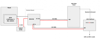
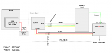
Does the below diagram look correct?
**Getting updated with comments from this thread

Manual for eg4 6k:
>CAUTION! Before connecting to AC input power source, install a separate AC breaker (0A max) between
inverter and AC input power source. Ensure the input breaker and conductor ratings match. Installation of a
breaker on the AC input is required for OCP and means of disconnect. Check with your AHJ and ensure correct
system design for regulatory compliance.
1) Do I need another 40A breaker between the AC input & Inverter? There is already a breaker on the Main panel. A little confused with the above statement
2) Will these work for 10awg?
3) What is the output amps for 6k? Will 40A work
Nominal Output Current 27.3A (for 110VAC)
25A (for 120VAC)
4) Can I run both the #10 AWG wires in a 1 inch conduit? (i.e. 4 wires total). Will it fit inside a 1/2 or 3/4 inch conduit?
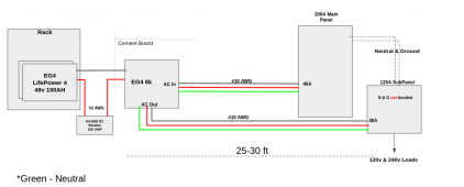
5) What wire size do I use for Neutral & Ground?
6) Will I be able to run a 40 amp AC unit with this? Looks like the max output is 40A from the inverter
7) I am thinking off getting the EG4 6k instead of the EG4 6.5k inverter since it is split phase so it supports 120v & 240v. Assuming this is correct?
8) Is there a discount code that I can apply for if I buy the whole thing together?
thank you
Growatt 5000 ES build/design. Help me help my neighbor!!
I'm doing my first build for a friend, and need help finalizing the design. He had ordered a bunch of parts last year, and he installed 5.2 kW of panels, but he doesn't know how to do the electrical and needed my help. He has a Growatt 5000 ES off grid inverter, Solar Edge 5k Auto transformer...
diysolarforum.com
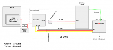
Does the below diagram look correct?
**Getting updated with comments from this thread
Manual for eg4 6k:
>CAUTION! Before connecting to AC input power source, install a separate AC breaker (0A max) between
inverter and AC input power source. Ensure the input breaker and conductor ratings match. Installation of a
breaker on the AC input is required for OCP and means of disconnect. Check with your AHJ and ensure correct
system design for regulatory compliance.
1) Do I need another 40A breaker between the AC input & Inverter? There is already a breaker on the Main panel. A little confused with the above statement
2) Will these work for 10awg?
3) What is the output amps for 6k? Will 40A work
Nominal Output Current 27.3A (for 110VAC)
25A (for 120VAC)
4) Can I run both the #10 AWG wires in a 1 inch conduit? (i.e. 4 wires total). Will it fit inside a 1/2 or 3/4 inch conduit?
5) What wire size do I use for Neutral & Ground?
6) Will I be able to run a 40 amp AC unit with this? Looks like the max output is 40A from the inverter
7) I am thinking off getting the EG4 6k instead of the EG4 6.5k inverter since it is split phase so it supports 120v & 240v. Assuming this is correct?
8) Is there a discount code that I can apply for if I buy the whole thing together?
thank you
Attachments
Last edited:


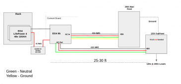
") . I have updated the diagram.
. I have updated the diagram.