No, I also have a transfer switch. I just didnt want to complicate the discussion on panels.Quick question, if I understand your system correctly, if/when you have issues with the inverters and needed to take them "offline" for repair/replacement then you'd lose all power supply to your home? Thanks.
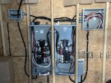
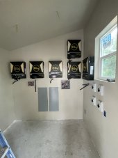
here is a pic of my system this is all in my workshop 100 ft from house
the AC in comes thru the left most conduit up from the floor. In the small junction box below the gutter and transfer switch I used morris split connectors to double each of the 4 wires. Then 1 set of AC input wires goes to the transfer switch and the other set goes to AC input on the inverters.
The AC output from the inverters goes to the transfer switch.
The transfer switch decides which power will go to the 125amp panel, located to the right of the transfer switch, which has the 60amp breaker going to the house panel
I did it like this so I could add some off grid outlets in the workshop at a later time
The middle conduit goin to the floor is the AC from the 60amp breaker going to the house
the conduit on the right is the incoming PV wires going to DC breakers before the inverters