I used a 500A/50mV (100uohm) shunt from my Victron BMV-712 as the battery shunt, and the 300A/75mV (250uohm) shunt from my Chargery as the solar shunt. Too large so not optimal for low currents especially on the solar shunt but it's what I have in my hands right now. I haven't tried to characterize accuracy just yet. Just compared between my power supply, my digital load, and my clamp DC ammeter. All match to 0.1A but I'm seeing a bit of noise and maybe quantization errors at very low currents. I'll take a closer look when my 280Ah cells come in next week.Good to know about the shunt calibration results. What shunts are you using? I may hook up my power supply to the PV shunt briefly to confirm SBMS amp reading matches supply amp reading and adjust resistances accordingly, if necc.


You are using an out of date browser. It may not display this or other websites correctly.
You should upgrade or use an alternative browser.
You should upgrade or use an alternative browser.
Electrodacus-based Build Begins
- Thread starter Dhowman
- Start date
On the wifi, a travel router device like this might help at least temporarily. Basically it creates its own wifi network, can connect and share another wifi network, and has an ethernet port for a wired network (actually 2: LAN and WAN).
(link)
I have one in the motorhome which when I am parked at home it automatically connects to my house wifi and is hardwired to a wired router in the RV with several devices connected. I can connect my phone or laptop to its wifi/SSID and access devices in the RV or the internet. When I am on the road, I turn on my iphone hotspot and the travel router automatically connects to that hotspot then all my devices in the RV can see each other and share the internet.
My thought is to have the travel router connect to the SBMS hotspot and then the wired or wifi network to connect other devices. You could connect to the travel router SSID to access all the devices. Access to the internet would required a wired connection to another bridge device. BTW it runs OpenWrt.
Update: Still trying to get just enough of my build done to begin capacity testing but feel like I'm getting close now. Having never built something like this before, I'm discovering things take wayyyyy longer than I thought and, of course, life interruptions haven't helped.
Perfect example of this is the amount of time it took me just to get those control wires all hooked up to the side of the SBMS: the better part of this past weekend. Dacian recommends CAT6 cuz it's twisted but CAT6 and the SBMS piece that accepts those are immensely fiddly to work with to put it mildly.
1. CAT6 wire is NOT designed to be stripped, or terminated with anything else but network plugs or push-down tools. It's just too thin. Even with the right stripper (Hesitant to click that link? Don't blame you! HAH!), it takes multiple attempts to get a clean end that hasn't removed one or two strands. When there are only 6 to begin with, that's a problem. And if you want all your leads to terminate at the same length, then you gotta snip any good ones you've made and start all over to get all 8 wires to the same length (so give yourself plenty of extra length for this when cutting your CAT6).
2. The original SBMS0 that I have (Dacian's got a new receptacle to take those wires in his new SBMS) is likewise not designed to take CAT6 (unless, per him, it's solid core ... has anyone ever seen solid core CAT6?). You have to insert a small pin to open a gate that allows you to insert those hair-follicle thin CAT6 strands and then remove the pin to capture the wire. Was only successful with about half the ones I tried this on and even those pulled back out with just a little tug. The other half refused to go in without just collapsing in the hole. Peering into those holes with a 10X loop (yes, that's what you need to see into those tiny holes), I realized that some had smaller openings than others. Ordered the ferrules he recommends to get around this, but while that stiffened up the wire to be able to force it in, some still wouldn't go all the way home and some just popped back out with just a little tug.
3. Before giving up entirely and just ordering the new SBMS0, I tried slightly larger wires and found that #18 hookup wire is perfect and probably what those holes were designed to accept. I then used ferrules just big enough to accept both the #18 and the CAT6 and spliced them together. (BTW, to get ring terminals on those CAT6 wires for the shunt connections, I also found that terminating them first with an #22-24 ferrule makes for a much better connection when crimping a ring terminal over it. Then tape the whole thing up for strain relief, cuz if you bend that CAT6 wire just a couple times at that terminal, it breaks off).
4. I also super glued DIN rail mounts to the back of my DSSRs. Works really well and makes the install MUCH easier (can remove/reposition those with ease).
Piccies (in no particular order)

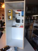
Project box w PV GFP breaker and inverter precharge lamp w momentary switch.
.JPG")
Inside of project box.

DIN mount adapters for DSSRs.


#18 pigtails at the CAT6 ends.


Project box w PV GFP breaker and inverter precharge lamp w momentary switch.
Inside of project box.
DIN mount adapters for DSSRs.
#18 pigtails at the CAT6 ends.
Attachments
Nice clean installation!Update: Still trying to get just enough of my build done to begin capacity testing but feel like I'm getting close now. Having never built something like this before, I'm discovering things take wayyyyy longer than I thought and, of course, life interruptions haven't helped.
Perfect example of this is the amount of time it took me just to get those control wires all hooked up to the side of the SBMS: the better part of this past weekend. Dacian recommends CAT6 cuz it's twisted but CAT6 and the SBMS piece that accepts those are immensely fiddly to work with to put it mildly.
Yes there are many good things about the SBMS0, but cable connections are not one of them. The CAT6 cables and miniature connecters are a joke, way too dainty for any mobile application. After messing with it during bench testing I am going with marine tinned 18/2 duplex cable. I like to follow ABYC standards for my mobile application and they specify 16 AWG minimum except can be 18 AWG if in a sheath and can extend up to 30 inches outside of the sheath. I will just use one 18/2 cable per device since there are generally two connections to the remote control.
One suggestion--consider using heat shrink tubing rather than tape around your CAT6 to 18 AWG connections. More robust. Or better yet you can get butt splice connectors with heat shrink tubing on them.
One more suggestion--hard to tell from the photo how you have the CAT6 wires secured. I would at least put a tie wrap around the group of splices to stiffen it up, and tie it to a standoff or a bigger stiffer cable. Will help stiffen it to protect from vibration. Again butt splices would be stronger and tie wraps around them work well.
mapguy525
Solar Enthusiast
Very nice and well thought out. Agree about using heat shrink, butt splices or gel splices for the small gauge wire. Plus supporting the splice locations.
Awesome work @Dhowman
I feel your pain when it comes to the finicky/fragile 1x10 connections to the SBMS0. This same frustration that you and others have expressed has manifested in the latest revision which changes the primary connector size and methodology. Stripping and terminating CAT5/6 or IDC cabling is simply a non-starter in my book.
In anticipation of my system build, I opted to layout an interconnecting PCB so I can make conventional compression terminal connections in a more reasonable and practical manner. I used 3.81mm pitch terminals for the design such that all the wiring required by the SBMS0 can wire up to the new terminals. All the connection to the BMS are via 2x5 and 2x6 IDC cables, along with (2) 1x5 2" flat flex cables that fit the 1x10 nicely.
The board has a collection of other niceties, like providing pull-up resistor power sourcing for the new DSSR20 version, providing jumper-able battery configuration for balance & monitoring (3S to 7S) removing all the requirements for the redundant wires otherwise required, and the design is 100% thru-hole reversible so it can mount adjacent to the SBMS0, or flip 180 and mount directly to the back of the unit on the same hardware centers.
I just went to open my EAGLE project for screenshots and last round of revisions to the silkscreens seem to have been lost? (grrrrrrrrr). I know they were complete cuz' I printed some proof sheets (I photographed those to post here). SO, looks like some do-over, and I'll get to that over the holiday weekend most likely...
Planning to make a 10-pc run and I will have some extra boards that I'd consider selling off to anyone interested when the time comes. These will be 1 oz. copper 0.0625 PCB's and they do have a ground-plane copper pour for battery/power negative. No via's, either in the layout.
Thanks @Airtime @mapguy525 @KohalaJim ... see my "lessons learned" reply to Dacian on this topic. Live and learn. ")
kimsv
New Member
- Joined
- Dec 29, 2019
- Messages
- 35
Thanks for sharing your build, looks very neat and tidy!2. The original SBMS0 that I have (Dacian's got a new receptacle to take those wires in his new SBMS) is likewise not designed to take CAT6 (unless, per him, it's solid core ... has anyone ever seen solid core CAT6?). You have to insert a small pin to open a gate that allows you to insert those hair-follicle thin CAT6 strands and then remove the pin to capture the wire. Was only successful with about half the ones I tried this on and even those pulled back out with just a little tug. The other half refused to go in without just collapsing in the hole. Peering into those holes with a 10X loop (yes, that's what you need to see into those tiny holes), I realized that some had smaller openings than others. Ordered the ferrules he recommends to get around this, but while that stiffened up the wire to be able to force it in, some still wouldn't go all the way home and some just popped back out with just a little tug.
I just wanted to comment on the CAT6 problem. Usually (at least here in Europe) CAT6, and other network cabling, are solid core if it is installation cable. Meaning it's for permanent installation in walls terminating in wall outlets. The multiple strand cables are for connecting devices to wall outlets.
kimsv
New Member
- Joined
- Dec 29, 2019
- Messages
- 35
Sorry, disregard my comment #28. I read the thread on Dacians forum that you link to where he explains.Thanks @Airtime @mapguy525 @KohalaJim ... see my "lessons learned" reply to Dacian on this topic. Live and learn.
John Simmons
New Member
- Joined
- Feb 1, 2020
- Messages
- 44
Sorry, disregard my comment #28. I read the thread on Dacians forum that you link to where he explains.
John Simmons
New Member
- Joined
- Feb 1, 2020
- Messages
- 44
I had similar issues with the fiddly tiny wires for ADC, and EXTIO3, and EXTIO4. I also had issues with the ribbon cable as my batteries were installed about 25 feet of wire run away from the SBMS0 (sailboat with batteries under a bunk and SBMS0 at the nav station).
For the tiny wires I had a large amount of 22AWG shielded cable, all stranded, not solid. It was left over from a Garmin antenna install project and I ended up using it, and it worked like a charm. The part that got shoved into the push lock connectors, I doubled over and soldered back on itself along with some heat shrink. Much stronger and more robust. I agree that cat5 and cat6 are VERY hard to deal with and extremely fragile, so I used the Garmin cable instead. I would love to see a stronger more rugged system for hooking up these wires. A small ring terminal type block would have made me much happier than the push lock connectors.
The second problem I had was that the voltage supply and sense wires on the SBMS0 on the flat cable need to be completely separated all the way from the battery to the Control unit. Remember, I had a 25 foot run, and I didn’t keep them all separate as I was trying to save wire and time. If you don’t keep them separate,the top and bottom cells read lower in voltage than the middle cells due to the small current drain of the SBMS0. Dacian was super fantastic to deal with. His support was invaluable in understanding the problem.p
Here is a copy of his response to my voltage sense problem. His advice was to keep everything close together, but for my problem of wanting the monitor at the Nav station, I had to go against his advice, and he STILL helped. Super technical support, I can’t say that enough.
*****************Quote from Dacian*************************
No matter the run length you need to have separate wires for pin 1 and 2 and for pins 10 and (11+12) The pin 1 and pins (11+12) will supply the power to SBMS0 and pins 2 and pin 10 will measure the cell voltage thus having separate wires for them will not create any voltage drop. And this is true no matter the length of wire even with the standard 1.8m cable each wire needs to get to the cell terminals.
**************End quote from Dacian **********************
After I ran separate power and ground cables, it all worked great.
The menu on the SBMS0, and electrical design, and support Dacian has is second to none. The only things I would like to see would be in the mechanical strength of the terminations, the mounting system, and the display size.
1) A larger flange around the outside of the unit, so you can make a bit more of a sloppy hole.
2) Mounting should be with 4 screws from the front not the plastic push bolts, if you have a blind hole, they don’t work.
3) They make 2 conductor twisted shielded pair wire, Xantrex uses it for their current shunt. It is a bit more expensive, but it takes 18 gauge ring terminals, and that would make connecting up EXTIO, EXTIO4, and the ADC super easy. It is a bit more expensive, but as everyone has said, Ethernet cable is just a bitch to work with and inspires no confidence. In my opinion it should not be recommended. Google “ 2 conductor 18 Gauge shielded twisted pair cable”
4) I also would have happily paid 3 x the price for the unit if the display was large enough to read without glasses. Dacian has a fantastic price point product that works awesomely, but my old eyes struggle to read those itty bitty numbers. He must have GREAT eyesight.
I really really like the performance of his controller and it is unlike anything else out there. I am sure he will keep innovating and making changes. He has been awesome to deal with and I have nothing but respect for him and his work.
John Simmons
S/V Bad Bunny presently in Panama.
Just joined the Electodacus club. Was going to go Chargery, but the Open Source"ness" of this appeals to the software geek in me and the external controls approach satisfy my need to NOT run hundreds of potential amps through a FET based solution. Batteries soon, BMS soon. Fun winter build on my 37' motorhome coming up. Excited...
Actually, the more I've thought about this since posting above, the less I think what I described is what was going on, but I just can't think why the terminals at the charger wouldn't come down to the battery voltage. Clearly the sensing wires can, but why my big fat charging wires would have such a big voltage drop and my #18 sensing wires don't has kind of got me stumped.
Any ideas?
The sense inputs are very high impendence so there is virtually no current flow through the senses wires.
The charging wires are passing current and that means voltage drop. That is why you power supply has sense inputs. This kind of 4 wire connection is called a Kelvin connection.

Four-terminal sensing - Wikipedia
Similar threads
- Replies
- 23
- Views
- 507