diy solar

diy solar

Electrodacus-based System Schematic (final version w detail)

Dhowman

San Diego, California
Joined
Dec 29, 2019
Messages
295
Location
San Diego
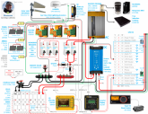
LFP cells arrived this week so have updated my schematic w all the inputs I've received since my original version.

Here it is (click the pic in this link for a higher rez version):
1586020182418.png

Changes, in no particular order:

1. Panels connected on roof via Anderson Plugs. Only showing one for each panel pair but there will be four (like this) at the panels and one at the entry point to the inside of the camper (that head to each of my 3 DSSRs). They will be keyed (and color coded), which will prevent things getting plugged in the wrong places.

2. As for adding some kind of current protection at my panels (question I had on this post), it's occurred to me after reading this, that it's probably not possible (or needed?). Optimum Operating Current for my Renogy's is 9.32A. Short Circuit Current is less than .5A more (9.71). Guess that's why they call 'em "constant current." ;-)

3. Surge Protection: Lots of evolution on my part since my original post and the post in #2. Best protection against a direct hit? Keep the truck/camper isolated from Earth. As for surges from nearby strikes, have added the gas tube arrestors on each antenna coax and included an SPD at my bus bar. If I do take a direct hit (as I have in the past), well, there's just nothing to be done about it.

4. Swapped my isolated DC converter (neeed 2 of 'em) for the non-isolated one above. Here's my rationale for that swap.

5. Fuses at battery were on POS terminal but then got this from Dacian (Electrodacus) when he saw that:

Disconnecting that battery switch will damage the current shunt amplifier inside the SBMS0. Same will happen if those fuses ever get damaged maybe by a short circuit.
All protection and disconnect should be after the current shunts not before ... or have that on the negative side.


N.B. for all those using SBMS ... do NOT allow POS side of battery to be disconnected when NEG is still connected!

6. Added a Disconnect Switch that will be accessible from the exterior of the camper to be able to quickly disconnect the battery should I need to (or when working in the electrical closet).

7. Related to #4, my original schematic had a 4 Channel Sonoff hanging off the 24V side of my DC converter, which would remain powered even after disconnecting the converter for LVC via EXTIO3. Oops! (And NO ONE caught that?? *grins*) With a lot more amps available w the new converter, I just moved all that to the 12V side and each have their own Sonoff SV switch (@24V, the original 10A 4 channel Sonoff was maxed; @12, I would have exceeded it 2x).

8. Spec'd all my breakers and wire sizes, and the Yagis. Wire and all associated bits and bobs and tools for wiring are now here. Just need to order the breakers and the antennas.

9. Have decided to go w a portable (vs inset) induction cooktop that I can use to cook outside the camper. Will likely rig up some kind of exterior outlet for this (one side of that double GFCI outlet for inside, one for outside). Similarly, will also likely wire a 12V external Anderson plug from my 12V panel for any outside 12V power needs I may have (it will be Red ... see #1, above).

10. Finally, added details for all my 12V consumers. This is the buck converter I will use and here's a link to video for converting Sonoff SV into Dry Contact Relay.

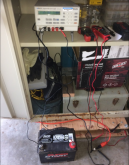
Will post separate thread for initial cell balancing that's about to commence. Picked up a pretty sweet used Fluke PM2811 linear power supply for $80. All it needed was a new fan, which I also found on eBay ($15 for 2). Swapped it out for the old one and tested it on an ancient car battery. Actually brought it back to life with some diligent CC and CV charging over the course of a couple of days. Super psyched!
1586026775678.png
 
Anybody else having this problem? Just tried it on 2 other computers (that I'm not signed into my Google acct on) and it comes up just fine. Not sure what might be happening.
No problems to view - nice job !
 
Hmmm ... just realized one can't edit a post once it's been quoted (?) In any event, I dropped a different YT vid about Sonoff rewiring for creating a Dry Contact Relay. One above is fine, but this one is much better.
 
Good work man, I'm excited to see your design is coming together and appreciate your commitment to documenting your progress. I'm still soaking in all the details from your schematic so I'll probably have more to say in the future, but for now, I just wanted to say good work!

I do have a couple preliminary questions:
  1. You have a somewhat unorthodox battery busbar, and battery cable configuration. I believe I understand your logic, but rather than guessing at it, I figured I'd ask about it.
  2. The 'buck' converter you linked to looks to be a 6A BOOST converter, was there another product you meant to link to?
  3. Can you explain how you are defining/calculating "max protected amps" for your wiring.

edit to add:
5. Fuses at battery were on POS terminal but then got this from Dacian (Electrodacus) when he saw that:

Disconnecting that battery switch will damage the current shunt amplifier inside the SBMS0. Same will happen if those fuses ever get damaged maybe by a short circuit.
All protection and disconnect should be after the current shunts not before ... or have that on the negative side.


N.B. for all those using SBMS ... do NOT allow POS side of battery to be disconnected when NEG is still connected!

Ive been researching the SBMS0 for a couple months now, you've been researching it for what, like 4-6 months? Its crazy to me that both of us could get this far along without knowing this. Its a little disconcerting really. Makes me wonder what else I might be overlooking that isn't explicitly spelled out in the manual or elsewhere.
 
Last edited:
Good work man, I'm excited to see your design is coming together and appreciate your commitment to documenting your progress. I'm still soaking in all the details from your schematic so I'll probably have more to say in the future, but for now, I just wanted to say good work!
Thanks!
You have a somewhat unorthodox battery busbar, and battery cable configuration. I believe I understand your logic, but rather than guessing at it, I figured I'd ask about it.
How so?
The 'buck' converter you linked to looks to be a 6A BOOST converter, was there another product you meant to link to?
Hah! Have gotten into the habit, and I'll blame it on @Will Prowse, of calling these boosting converters "buck" instead of "boost." Been doing it ever since I watched this about powering devices that rely on AC adapters directly from DC. Product is the right one. "Buck" in my diagram should really be "Boost." Making updates to the diagram Dacian's given me and will include that one. (y) That product is rated for 100W w a max input of 9A. Biggest jump I need to make is 12>20V, so I'll get a little north of 5A out of it (@20V) which a) is less than the converter's max amp output rating and b) meets the output current rating I need. I'll be using one for each device.
Can you explain how you are defining/calculating "max protected amps" for your wiring.
In most cases it's the smaller of 1) max load or charge those wires will experience given list of my consumers and output of my chargers respectively and 2) max current a device on that line is rated to support (e.g. "peak" currents, if only for short duration). In a some cases it's the later even if loads and/or charging is less than what I can expect from my current configuration but I may want to increase either or both at a later time.
Oh, and it also factors in wire lengths ... I've got a CAD drawing of where all these things will live so I have a pretty accurate measurements. I've been using this to confirm I'm good on gauge for specified length and expected current.
Ive been researching the SBMS0 for a couple months now, you've been researching it for what, like 4-6 months? Its crazy to me that both of us could get this far along without knowing this. Its a little disconcerting really. Makes me wonder what else I might be overlooking that isn't explicitly spelled out in the manual or elsewhere.
I suspect you're referring to "do NOT allow POS side of battery to be disconnected when NEG is still connected!" Yeah, I got wind of this in the comment thread I have a screenshot of on this post. I'm not too concerned about anything else. Dacian's had a look at my schematic and it "looks good" since I moved fuses and the disconnect to NEG side.
 
You have a somewhat unorthodox battery busbar, and battery cable configuration. I believe I understand your logic, but rather than guessing at it, I figured I'd ask about it.

I was referring to the dual busbar, dual main battery wire configuration. dual fuse, topology:
Screenshot_2020-04-04 New photo by Howard Snyder.png
It looks very robust. But I don't believe I've seen that specific topology before, but I haven't spent much time looking at xPxS topologies so many this is a more common config than I assumed?

Hah! Have gotten into the habit, and I'll blame it on @Will Prowse, of calling these boosting converters "buck" instead of "boost." Been doing it ever since I watched this about powering devices that rely on AC adapters directly from DC. Product is the right one.

Ah okay I get it now. I was misunderstanding the purpose, I thought you were using these little converters to step down from 24v to 12v (forgot you are using the Orion for that). But now I see the purpose of these little suckers will be to replace all your AC adapters. I like this, I'm planning to do the same with as many devices as I can.

In most cases it's the smaller of 1) max load or charge those wires will experience given list of my consumers and output of my chargers respectively and 2) max current a device on that line is rated to support (e.g. "peak" currents, if only for short duration). In some cases it's the latter even if loads and/or charging is less than what I can expect from my current configuration but I may want to increase either or both at a later time.

Am I correct in assuming that this was meant to read "Max ProJected Amps" not "Max ProTected Amps"

I suspect you're referring to "do NOT allow POS side of battery to be disconnected when NEG is still connected!" Yeah, I got wind of this in the comment thread I have a screenshot of on this post. I'm not too concerned about anything else. Dacian's had a look at my schematic and it "looks good" since I moved fuses and the disconnect to NEG side.

I really appreciate how responsive and straightforward Dacian is, and he put together a really solid manual (though I wish it had a little more meat on the bones in some places). The only frustrating thing about designing around the SBMS0 is that (for how unique it is) there is so little information out there about it and so few examples to learn from. The information that is out there (outside of the manual) is pretty scattered, I wish there were some sort of official or unofficial community hub, or owners group/mindshare, and repository of information. That's what I was hoping to jumpstart with 'The Solar BMS thread' but I'm not sure the forum has quite reached the critical mass of active members using or building with the SBMS to get that ball rolling. We'll see though, there is a lot of interest in it, and I'm sure Will's video the SBMS will definitely increase interest and visibility.
 
So, here's a list-o-things I need to change in that diagram so far:
1. Change "buck" to "boost".
2. Attach the SBMS sensing wires to the sensing posts on shunts, not the terminal ends (they're in the wrong place in the pic above). I knew this but just put 'em in the wrong location on the diagram.
3. Dacian's recommended up-ing the PV breakers:

... seen 12A from a single 260W panel in a very cold and sunny afternoon with edge of cloud effect and you can have 10A for minutes or hours and so 25A breakers will get hot and likely trip so 32A breakers will be a better idea for each group of two panels.
4. May also be making tweaks to the shunt specs. Asking him for clarification on that too per this in user manual.

The ADC1n/ADC1p input can read in the -90mV to +90mV range so can read current in both directions while the PVp/PVn current shunt can read
current in a single direction, 0V to +90mV, thus to best take advantage of this range a 75mV current shunt can be used but 50mV current shunts and
100mV current shunts will also work

75mV falls in that range but I think there are tradeoffs that I'm trying to understand e.g. I think higher mV's means greater resistance which means they'll run hotter? Just trying to better understand interplay btw A and V rating of shunts together w V measurement accuracy of SBMS. There's probably a sweet spot for the system spec'd above. Trying to understand how best to hit it.
 
I was referring to the dual busbar, dual main battery wire configuration. dual fuse, topology:
View attachment 10310
It looks very robust. But I don't believe I've seen that specific topology before, but I haven't spent much time looking at xPxS topologies so many this is a more common config than I assumed?
It was either 1-1/0 wire or two #1s. The 1/0 would be tougher to bend around what I need it to bend around than the #1. Would also need a bigger crimper and lugs than I have. Plus, already have the #1. Would have to buy the 1/0 and corresponding lugs. I have two posts at each terminal anyway. Might as well use 'em both.
Am I correct in assuming that this was meant to read "Max ProJected Amps" not "Max ProTected Amps"
Probably not the clearest way to communicate what I was shooting for there. I meant "protected" in the sense that, between wire gauge and circuit protection, I was "protected" at those current ratings. I'll come up with a better way to say that and make the necessary mod.

Thanks, btw, for that "eagle eye" of yours!
 
  • Like
Reactions: Dzl
4. May also be making tweaks to the shunt specs. Asking him for clarification on that too per this in user manual.

The ADC1n/ADC1p input can read in the -90mV to +90mV range so can read current in both directions while the PVp/PVn current shunt can read
current in a single direction, 0V to +90mV, thus to best take advantage of this range a 75mV current shunt can be used but 50mV current shunts and
100mV current shunts will also work

75mV falls in that range but I think there are tradeoffs that I'm trying to understand e.g. I think higher mV's means greater resistance which means they'll run hotter? Just trying to better understand interplay btw A and V rating of shunts together w V measurement accuracy of SBMS. There's probably a sweet spot for the system spec'd above. Trying to understand how best to hit it.

Yeah, this is something I need further clarification on too. I have the vague impression that 'lower is better' so long as max continuous current is ~75% of the shunt's rated current. This is based on two vague understandings (1) lower mV = higher 'resolution' current monitoring (2) lower mV = less resistance = less losses/less heat. This is based on preliminary research I did a while back so the details are hazy and quite possibly not even correct.

I definitely need to do more research, and I'd like to understand what dacian means about taking maximum advantage of the range.

edit: some relevant discussion of the workings of shunts in the Chargery thread (posts #127-133) and in this thread (posts #26-32)

Thanks, btw, for that "eagle eye" of yours!

No problem(y). Thanks again for taking the time to document your design and build process in such detail. As I said above, there aren't a great deal of examples out there to learn from and get inspiration from, so your example has been very valuable to me, and I've spent many minutes pouring over your earlier draft, and refer back to your diagrams often as I design my own system.
 
Last edited:
Thanks!

How so?

Hah! Have gotten into the habit, and I'll blame it on @Will Prowse, of calling these boosting converters "buck" instead of "boost." Been doing it ever since I watched this about powering devices that rely on AC adapters directly from DC. Product is the right one. "Buck" in my diagram should really be "Boost." Making updates to the diagram Dacian's given me and will include that one. (y) That product is rated for 100W w a max input of 9A. Biggest jump I need to make is 12>20V, so I'll get a little north of 5A out of it (@20V) which a) is less than the converter's max amp output rating and b) meets the output current rating I need. I'll be using one for each device.

In most cases it's the smaller of 1) max load or charge those wires will experience given list of my consumers and output of my chargers respectively and 2) max current a device on that line is rated to support (e.g. "peak" currents, if only for short duration). In a some cases it's the later even if loads and/or charging is less than what I can expect from my current configuration but I may want to increase either or both at a later time.
Oh, and it also factors in wire lengths ... I've got a CAD drawing of where all these things will live so I have a pretty accurate measurements. I've been using this to confirm I'm good on gauge for specified length and expected current.

I suspect you're referring to "do NOT allow POS side of battery to be disconnected when NEG is still connected!" Yeah, I got wind of this in the comment thread I have a screenshot of on this post. I'm not too concerned about anything else. Dacian's had a look at my schematic and it "looks good" since I moved fuses and the disconnect to NEG side.
I think that was the only time in my life I called it that because it was a buck/boost converter. It could go higher and lower.

I am deleting that video because you were confused by it. It was both a buck and a boost converter, but used as a boost converter. That video will be gone for all time now. Thanks.
OH, no. Don't do that! My comment was kind of tongue and cheek. And that video was pretty valuable insofar as it's helped me to move about half of all my stuff to DC. Buck ... Boost ... who cares? Except Dzl. ;)
 
  • Haha
Reactions: Dzl
Did I see a 1600 W induction cook-top powered by 2000 W Inverter??:unsure:
Looks like you could utilize a bigger Pure Sine Inverter for some serious cooking @1600W.
Induction require substantially more load than what it shows in the "cook settings" plus
spikes generated by switching of induction appliances could be detrimental to the Inverter
as well as other devices plugged in line. And apologies if I missed spotting a Charge controller in the system.

Edit: Is the DC converter functioning as Charge Controller
- in that case - many things would need to be managed manually.

Nicely documented(y)
 
Last edited:
And apologies if I missed spotting a Charge controller in the system.

The 3 green and orange devices top-middle labeled DSSR20 are the charge controllers. Made by the same guy that makes the BMS
 
The 3 green and orange devices top-middle labeled DSSR20 are the charge controllers. Made by the same guy that makes the BMS
Thanks for the heads-up, they looked like SSR relays at the first glance! Are they rated for 40Amps?
 
Thanks for the heads-up, they looked like SSR relays at the first glance! Are they rated for 40Amps?

Yeah they certainly don't look like SCC's do they. The Electrodacus stuff is very unique (in look and in design). I believe each controller is designed for 2 x "24 volt" 60 or 72 cell panels.
 
Yeah they certainly don't look like SCC's do they. The Electrodacus stuff is very unique (in look and in design). I believe each controller is designed for 2 x "24 volt" 60 or 72 cell panels.
Okey....looks like some current switching relay, more like a PWM circuit. Do we have a thread or some other source for additional info on that device?
That BMS for sure is something to watch out for.
 
Okey....looks like some current switching relay, more like a PWM circuit. Do we have a thread or some other source for additional info on that device?
That BMS for sure is something to watch out for.

Here is the thread for the SBMS, that's the BMS portion, but there is a decent bit of discussion about the charge controller portion as well. I personally don't know a ton about them other than that they are cheap, reliable, and not MPPT but also not technically PWM. In the top post of the thread I linked to you will find links to the creators website and youtube channel.
 
Last edited:
Did I see a 1600 W induction cook-top powered by 2000 W Inverter??:unsure:
Looks like you could utilize a bigger Pure Sine Inverter for some serious cooking @1600W.
Induction require substantially more load than what it shows in the "cook settings" plus
spikes generated by switching of induction appliances could be detrimental to the Inverter
as well as other devices plugged in line. And apologies if I missed spotting a Charge controller in the system.

Edit: Is the DC converter functioning as Charge Controller
- in that case - many things would need to be managed manually.

Nicely documented(y)
Hey, thanks @Bhupinder . It's funny, but the SBMS/Prosine/True Induction combo I've spec'd is the ONLY combo that I know has been in regular use over a long period of time by Everlanders, so I'm pretty confident they'll work very nicely together. Actually, more confident in that combo of products in my design than anything else that's there! ;)
 
Back
Top