diy solar

diy solar

Electrodacus-based System Schematic (final version w detail)

The reason for use of a Class T or equivalent fuse is quite bit more detailed in the Samlex Evo owners manual link in the resources section:
3.5.4 Fuse Protection In The Battery Circuit A battery is an unlimited source of current. Under short circuit conditions, a battery can supply thousands of Amperes of current. If there is a short circuit along the length of the cables that connects the battery to the inverter, thousands of Amperes of current can flow from the battery to the point of shorting and that section of the cable will become red-hot, the insulation will melt and the cable will ultimately break. This interruption of very high current will generate a hazardous, high temperature, high-energy arc with accompanying high-pressure wave that may cause fire, damage nearby objects and cause injury. To prevent occurrence of hazardous conditions under short circuit conditions, the fuse used in the battery circuit should limit the current (should be "Current Limiting Type"), blow in a very short time (should be Fast Blow Type) and at the same time, quench the arc in a safe manner. For this purpose, UL Class T fuse or equivalent should be used (As per UL Standard 248-15). This special purpose current limiting, very fast acting fuse will blow in less than 8 ms under short circuit conditions. Appropriate capacity of the above Class T fuse or equivalent should be installed within 7” of the battery Plus (+) Terminal (Please see Table 3.1 for fuse sizing). Marine Rated Battery Fuses, MRBF-xxx Series made by Cooper Bussmann may also be used. These fuses comply with ISO 8820-6 for road vehicles.

MRBF fuses are great idea, but can add stress to battery terminals due to stacking and vibration. This is more an issue in mobile environments than stationary environments
 
Last edited:
Fuses, only on the negative side work but don't protect the entire wiring/components system, as completely in a catastrophic event.

As long as the OCP device is close enough to either terminal to minimise the risk of a short upstream then I don't see a difference.
What am I missing?
 
As long as the OCP device is close enough to either terminal to minimise the risk of a short upstream then I don't see a difference.
What am I missing?
in simple terms...
Reduce the momentary inrush potential for the all the wiring and electronics prior to fuse disconnect. Remember dc flows from positive to negative. Putting the OCP at the end of the loop, instead of the front of loop exposes the system to a few more milliseconds of current/voltage.

Electricity flows at ~280,000,000 meters per second.
 
Electricity flows at ~280,000,000 meters per second.
Understand that fact. A couple milliseconds can put electronics or a marginal sized wire at risk.

EDIT: I have done catastrophic OCP both ways, positive/negative and seen the results of a user created catastrophic event of both wiring methods.
Functionally, the negative catastrophic OCP systems had more damage to find and fix.
 
Last edited:
This video shows 8 awg wire with a 300 amp fuse.


Wire doesn't even get warm.
 
This video shows 8 awg wire with a 300 amp fuse.


Wire doesn't even get warm.

Fusing is on the positive side here. Would like to see the same experiment run with fusing on negative side.

My comments are towards catastrophic events, not individual circuit protection.

milliseconds / nanoseconds aside - from my experience catastrophic OCP just works better on the positive side.
 
milliseconds / nanoseconds aside - from my experience catastrophic OCP just works better on the positive side.

So you how many catastrophic events have you witnessed?
What was the ratio of positive fuse to negative fuse?
 
In installations with inverters that can draw large amounts of current, a catastrophic event fuse should be on the main positive battery connection. This way it protects everything from the fuse output point to the negative battery post. Fuses, only on the negative side work but don't protect the entire wiring/components system, as completely in a catastrophic event.

This is a design limitation dictated by the SBMS0, to avoid potentially damaging the BMS, switches and OCP cannot be placed between the batteyr + and the shunts. So the two logical next best places are directly after the shunts or on the negative battery terminal. Neither are ideal in my opinion, I'm still a bit uncomfortable with this situation, but I"m also still learning and brainstorming, so my opinion will likely evolve.

"If using a fuse, we recommend using a Class-T type or equivalent. This fuse type is rated for DC operation, can handle the high short circuit currents, and allows for momentary current surges from the inverter without opening."

The Samlex manual gives the same advice (Class-T or MRBF), both of which are approved by the ABYC for main battery overcurrent protection.

One thing I have noticed over the years, Low end and low-mid level inverter owners manuals are very slim on over current protection guidance.

Even some top tier companies leave much to be desired. Victron (a company I really like overall) can be tenaciously non-specific concerning safety information (OCP, Grounding, GFPD, etc).
 
So you how many catastrophic events have you witnessed?
What was the ratio of positive fuse to negative fuse?
2 service trucks. Both with large inverter systems. Both systems had the same user/operator who thought some poorly placed jumper wires would eliminate inverter shutdown in an overload situation.
 
This is a design limitation dictated by the SBMS0, to avoid potentially damaging the BMS, switches and OCP cannot be placed between the batteyr + and the shunts. So the two logical next best places are directly after the shunts or on the negative battery terminal. Neither are ideal in my opinion, I'm still a bit uncomfortable with this situation, but I"m also still learning and brainstorming, so my opinion will likely evolve.


The Samlex manual gives the same advice (Class-T or MRBF), both of which are approved by the ABYC for main battery overcurrent protection.


Even some top tier companies leave much to be desired. Victron (a company I really like overall) can be tenaciously non-specific concerning safety information (OCP, Grounding, GFPD, etc).

SBMS0 seemed like a great BMS system in many ways, but i don't like the inability to put catastrophic OCP on positive side. I understand that the SBMS0 developer has reasons for the design choices that were made.
 
SBMS0 seemed like a great BMS system in many ways, but i don't like the inability to put catastrophic OCP on positive side. I understand that the SBMS0 developer has reasons for the design choices that were made.

I am also dissapointed by this. I would clarify though, that its not that you can't put it on the positive side, its just that you can't put it on the positive side between the battery and the shunts

I brought this up to Dacian in an e-mail:
DZL said:
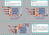
I have recently learned that placing a switch, breaker, or between the batteries and shunts would damage the SBMS0. I had been planning to locate a master battery disconnect switch and a main battery fuse off of the positive battery terminal (this is the best practice for marine electrical systems, which is the standard I am building towards). I see two alternatives both with their own downsides ( 1. locating the fuses and switches on the positive side 'downstream' of the shunts, or 2. locating the master disconnect switch and main fuse on the negative terminal of the battery). Both of these solutions seem non-optimal, but I admittedly only have a basic understanding of electricity and electrical safety. What do you consider the best practice for overcurrent protection for systems built with the SBMS. I have attached a basic diagram of the possible circuit protection configurations for my system.

options-smll.png

DACIAN "ElectroDacus" said:
The option B is what I recommend in the user manual. The current shunts will be very close to the battery is not even inside the battery box so it can be considered a panel installation it will be impossible to make a short circuit before or on the current shunts as there will be no negative path anywhere close to that any short can happen just after the circuit breakers or fuses. For extra protection you can add a much large value fuse on the negative side just after the negative battery terminal.
Also you can have two separate breakers one for inverter (or fuse for inverter) and one for DC circuits.

My reservations weren't completely assuaged by his answer, but I do think its a smaller risk than I first felt it was if properly designed.
 
can you explain what you did with the 2 shunts?

The short answer (explained in more detail in the post Dhowman linked to and in the SBMS manual) is that the dual shunt configuration is the recommended configuration and a distinguishing feature of the SBMS.
  • A single shunt lets you measure net current flowing in/out of the battery but you can't see current in and current out individually. It is enough to calculate state of charge, and know whether current is flowing in or out, but not to know what your load current or charge current is.
  • Dual shunts lets you measure net current and state of charge, AND current flowing in, as well as calculate current flowing out. So on top of the data a single shunt measures, the dual shunt can accurately measure charge and discharge current.
 
I am also dissapointed by this. I would clarify though, that its not that you can't put it on the positive side, its just that you can't put it on the positive side between the battery and the shunts

I brought this up to Dacian in an e-mail:


View attachment 12341
DACIAN "ElectroDacus" said:
The option B is what I recommend in the user manual. The current shunts will be very close to the battery is not even inside the battery box so it can be considered a panel installation it will be impossible to make a short circuit before or on the current shunts as there will be no negative path anywhere close to that any short can happen just after the circuit breakers or fuses. For extra protection you can add a much large value fuse on the negative side just after the negative battery terminal.
Also you can have two separate breakers one for inverter (or fuse for inverter) and one for DC circuits.


My reservations weren't completely assuaged by his answer, but I do think its a smaller risk than I first felt it was if properly designed.

That answer doesn't make me warm and fuzzy regarding the exposure of cabling/electronics in a catastrophic event.
 
I'm following this closely as I'm also in the pre-build, part collecting phase of an off-grid SBMS project... I'm wanting now to bring this up with the Dacian directly so I can understand the specific failure mode. It's smelling anecdotally somewhat akin to mitigating inductive current via a flyback diode when the inductive power source gets shutoff.

And to @Dhowman, nice engineering work and top-down design with your build...

I'm going out on a limb with my SBMS build and will be attempting to incorporate a wind turbine with my solar, experimenting with my own diversion load/control techniques. We have amazingly reliable trade winds, so PM recharging in the dark is a big plus for my system goals.
 
Back
Top