diy solar

diy solar

Electrodacus-based System Schematic (final version w detail)

It was either 1-1/0 wire or two #1s. The 1/0 would be tougher to bend around what I need it to bend around than the #1. Would also need a bigger crimper and lugs than I have. Plus, already have the #1. Would have to buy the 1/0 and corresponding lugs. I have two posts at each terminal anyway. Might as well use 'em both.

It may not be an issue for your installation, but you might find that the sum of the parts is less than the whole - that the capacity of two parallel cables is less than the capacity of a single cable of the same effective cross sectional area. Differences in the quality of the terminations and cable lengths will lead to one of the pair carrying more current than the other. Whether the difference is material or not depends on how much variation is tolerable for your design.

Also, there can be problems when of the pair suffers an insulation fault: the fuse, if rated to the larger "effective" cable rating, will likely allow a fault current that can exceed the smaller component cable's rating. Again might not be a problem for small contained runs where that fault is unlikely.
Thanks. I'm relying on this to ID the minimum wire gauge size when combining. With the very short runs I have (<5 ft), think I'm good but have also exceeded (by a couple sizes at least) the minimum size required for the combined gauge spec. And, yes, I'm fusing each of the combined lines to a) stay under the amperage rating of the individual wires and b) to cover the max amperage I'm expecting on those circuits that need to be carried by the pair.

So, for example, for my negative battery leads that I'm expecting 120A max on, I'd need 1 #6 or 2 #8 to keep my voltage drop at or under 1%. Since I already have #1 and #10 wire and doubling up the later wouldn't get me to that "effective" #6 minimum, I'm going with the #1 wire there.

Why two though? I don't know. Could probably get away with just one (and may just do that), but since there are 2 posts I can attach to, thought I'd just attach to both and fuse each with a single 100A fuse, keeping the amps well below what each of those wires are spec'd for and the combined fused amperage (200A) above what I'm expecting the max amperage to be. In fact, even if something were to happen to one of those #1s, the remaining #1 will be fine carrying all 120A. Only prob may be that the 100A fuse on that line may blow. Probably not a bad thing.

I think this is all pretty conservative and likely to cover all my safety bases as far as sending any amps across things they're designed to carry (and I can expect they would be carrying).

And on one final note, this may be totally misguided, but having seen thermographs of batteries experiencing high C rates, the hottest part is at the NEG battery terminal. Terminating on both NEG terminals of my last cell pair in the pack may help to more evenly distribute this "load."
 
... Could probably get away with just one (and may just do that), but since there are 2 posts I can attach to, thought I'd just attach to both and fuse each with a single 100A fuse, keeping the amps well below what each of those wires are spec'd for and the combined fused amperage (200A) above what I'm expecting the max amperage to be. In fact, even if something were to happen to one of those #1s, the remaining #1 will be fine carrying all 120A. ...

Heh, if you're going to do something well, may as well overdo it! Sounds like you're taking a sensible approach in so far as each individual cable would be safe in a pinch. As you note, adding capacity to reduce power loss can be a good efficiency measure even if not required for safety.

TBH, I mainly made the earlier post as I had once planned to run multiple parallel cables over a substantial part of a length of a van but had to rethink that plan when I considered what would happen in some failure modes (particularly the insulation failure...).
 
TBH, I mainly made the earlier post as I had once planned to run multiple parallel cables over a substantial part of a length of a van but had to rethink that plan when I considered what would happen in some failure modes (particularly the insulation failure...).

If the parallel wires have individual overcurrent protection at the charge source I don't see anything horrific about an insulation failure.
Maybe I'm not seeing it, what am I missing?
 
If the parallel wires have individual overcurrent protection at the charge source I don't see anything horrific about an insulation failure.
Agreed all may be well if you fuse separately; caveat: more junctions within parallel cable paths mean more potential variation between the resistance of those paths, and thus less equal current distribution - not a problem if any single cable is good for the entire load and you're doing this to minimise losses.

The situation I was looking at was from an existing fused connection - an "auxiliary battery" connection post, fused, from the vehicle's battery - no real option to fuse each individual cable. I was considering that option both as I had enough suitable smaller cabling to hand, but more to do with physical constraints - I had enough space to fit a couple of smaller cables over slightly varying paths, but it was a royal pain to run one larger one.
Basically, at the time the overload/failure problems didn't cross my mind, "of course parallel cables will work the same as a larger cable with the same area, it's basic electrical theory" :)
 
Because it seems like you have devoted more time than most to thinking through and designing safety into your system, I'm wondering if you have any thoughts on ground fault protection. Its something I've been intending to devote some time to learning about, but so far haven't found the time.

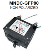
Apparently since 2008, NEC code has required PV arrays to incorporate a ground fault protection device (GFPD) such as this one from midnite solar, but I haven't heard much talk about it, and I haven't come across anyone here building GFP into their systems (other than GFCI outlets on the AC side).

Do you have any thoughts on this class of safety device? Did you consider adding GFP to your system at any point in your planning?
OK, that GFP breaker is on its way from N. Arizona Wind and Solar, along with all the other breakers in my updated design (see below). Thank you @Dzl for pointing me to that product.

Because I had a hard time sourcing the Schneider breakers, and they didn't have a similar GFP breaker solution anyway, I moved to all MidNite CBs in my updated design (below). So now, panels and arrestors are grounded to camper chassis but I'm keeping Inverter chassis & DC distribution grounds on the NEG bus.

So, you might ask, why not ground everything to Camper chassis? Well, I would if I put a similar GFP breaker on my load side but MS doesn't make one rated for those amps (would need to be 150-200A). I'll keep my eyes out for one, but I think I'm good for now. In the meantime, keeping those load grounds on NEG bus will trip my 100A or 50A breakers if either short to anything but the camper chassis. If they DO short to camper chassis, I expect that GFP will trip, but that isn't going to open my load CBs, so no protection offered by doing that.

Also, FYI, the MS GFP will only work if NEG bus is isolated from chassis ground, so if that 1/2A breaker sees any potential, it'll open the 80A breaker.

Additionally, I've added an Inverter Precharge solution to keep my battery Disconnect Switch and Inverter Breaker from arcing when inverter caps reload when either of those get closed and those caps need to recharge. While doing that may be fine on occasion (& @Will Prowse does it all the time ;)), do it enough times and those switches will fail & you may not know it if/when they do (or you will know it but only because one or the other don't work anymore i.e. bad things happen). Solution recommended to me by someone on ED forum is a small 36V/25W lamp wired in parallel with the Inverter breaker and accompanying small dedicated switch and fuse -- you want to be able to turn it OFF after the caps are charged but before your inverter is turned back ON to keep inverter from sensing a LV condition caused by the lamp.

Also, instead of Inverter and DC2DC sharing the same EXTIO3 LVC cutoff switch, I'm tapping into the back of SBMS0 to use EXTIO5 so each has a dedicated EXTIO cutoff (one on #3 and one on #5).

I'll update my battery story on separate post, but short of the long of it is: BLS informs me they're in LA now so looking to receive those in the next few days, at which point I'll have everything to begin building out this new design except for some of the 12V distribution bits, induction cook top and LTE router/antenna. Ideally, I could begin balancing/cap testing this weekend and probably complete the camper build by end of June (assuming all the solar stars align ... I know, redundant!).

Changes applied (yellow-highlighted below). Click the pic in this link for a higher rez version of this update (w/o the change highlights).
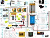
Schematic 20200517.JPG
 
Last edited:
It might be a silly question but I'm trying to get my head around your layout...

Your Camper Roof Array has max 10A running to max 20A cable which connects to a 30A MCB.
Your Trailer Roof Array has the same.
I assume your Future Array is likewise cabled and MCB'd.

Don't each of these arrays output a different (and progressively larger) amperage? For example, your Future Array indicates it will be 60A(?). I figure you'll never likely see those maximum outputs but was just wondering if that was why they're all the same cable/MCB ratings?

Also, what's the purpose of the GFP breaker? I've not seen one on any other vehicle mounted system I've looked at before (or if I have I didn't know what it was)?

the MS GFP will only work if NEG bus is isolated from chassis ground, so if that 1/2A breaker sees any potential, it'll open the 80A breaker.

When would this event likely happen?
 
It might be a silly question but I'm trying to get my head around your layout...

Your Camper Roof Array has max 10A running to max 20A cable which connects to a 30A MCB.
Your Trailer Roof Array has the same.
I assume your Future Array is likewise cabled and MCB'd.

Don't each of these arrays output a different (and progressively larger) amperage? For example, your Future Array indicates it will be 60A(?). I figure you'll never likely see those maximum outputs but was just wondering if that was why they're all the same cable/MCB ratings?

Also, what's the purpose of the GFP breaker? I've not seen one on any other vehicle mounted system I've looked at before (or if I have I didn't know what it was)?


When would this event likely happen?
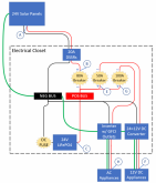
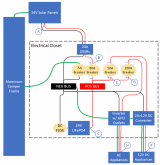
Each pair of panels (pair on roof, pair on camper and future pair) puts out 2x9.3A (Imp) so just under 20A each, so each pair is connected to a single DSSR20 (rated for 20A, so it's maxed) and a 30A breaker (20 x 1.25 = 25A but went to 30A for the breaker cuz I could, w cloud edge effects on colder days, get too close to 25A going through that 25A breaker, so went for 30A).

Total charge amperage from all 3 is 60A. That 60A comes off the bus (w the 3 DSSRs attached) and through the 80A side of that GFP breaker pair. The high current side is an 80A breaker (60A x 1.25 = 75A ... so went with 80A for those exceptionally high current scenarios but still not more than the wire can handle).

What does the GFP provide? Without one where I have it now, shorts (to GRND or NEG) along A>B might blow the DC Fuse or maybe trip the 80A breaker (even though it's polarized to work in the opposite direction) but there's a lot of wire involved in that short. [Omitted the 3-30A breakers cuz they're kinda redundant for the purposes of this discussion.]

1590097562709.png

With the GFP solution (.5A breaker ganged with 80A breaker) ...

1590097061191.png

... those shorts will always trip my 80A breaker and will do so very quickly. Battery, Panels and DSSRs are much less involved and virtually no surge. Any potential between GRND and NEG and that .5A breaker will instantly trip and open the 80A one when it does. Rated at only .5A, I think it would probably even trip for a double fault.

PV GFPs like this are actually required for NEC compliance. What that particular breaker does in my design is a little more complicated but you can immerse yourself in all the gory details here. ;)
 
Last edited:
For extio3 do you connect to negative battery on the – side an then does the sbms0 float the + side if it wants to turn off the device? I"m trying to figure this out because I need to connect to several devices to the extio3. I get my bms in the next few weeks after blowing up my first unit by a wiring mistake.
 
Because I had a hard time sourcing the Schneider breakers, and they didn't have a similar GFP breaker solution anyway, I moved to all MidNite CBs in my updated design (below). So now, panels and arrestors are grounded to camper chassis but I'm keeping Inverter chassis & DC distribution grounds on the NEG bus.

So, you might ask, why not ground everything to Camper chassis? Well, I would if I put a similar GFP breaker on my load side but MS doesn't make one rated for those amps (would need to be 150-200A). I'll keep my eyes out for one, but I think I'm good for now. In the meantime, keeping those load grounds on NEG bus will trip my 100A or 50A breakers if either short to anything but the camper chassis. If they DO short to camper chassis, I expect that GFP will trip, but that isn't going to open my load CBs, so no protection offered by doing that.
Nice design overall, I'll just comment on the chassis grounding. I've been researching this myself for my own van installation.

First DC. You do in fact have everything grounded to the chassis. Your negative bus connects to your non-isolated DC-DC converter negative which connects to your alternator negative which is connected to the chassis. Then your green safety grounds for your inverter and DC-DC converter connect to the negative bus bar which is connected to chassis as described above.

The Xantrex manual says "Recreational Vehicle Installations: Use #8 AWG or larger copper wire (green if insulated) and secure it to the chassis ground lug as well as the grounding point in your vehicle (usually the chassis)." The reasoning is that if positive shorted to the inverter chassis somehow (either inside or outside of the inverter), then the safety ground could end up carrying short circuit current until the inverter protection trips. #8 is big enough to handle that short duration high current until a breaker or fuse trips. #8 is considered OK for RVs but not boats, I believe because it is assumed it will be a short run to a vehicle chassis ground connection. In boats they say safety ground wire same size as DC input wire (as your Xantrex manual also says), I believe because a boat can be fiberglass (and large) and the run could be much longer.

For a non-shore connected system, the grounding point could be just the house negative battery terminal, not the vehicle chassis, with the entire house electrical system floating (they do say usually the chassis). I know many people do that. But as I mentioned above, you already have it tied to the vehicle chassis chassis via your non-isolated DC-DC converter and alternator. Personally I think it's better to have a direct separate path for inverter safety ground to a good vehicle chassis ground, fewest connections possible. And then if you ever do change to using shore power in the future you're already set.

For AC, it appears your inverter does not have a transfer switch for shore power or hardwired AC subpanel--just a GFCI outlet on the inverter. Is that correct? If you are standalone inverter-only, you are floating and the built-in breaker and GFCI outlet is fine. But if you do plan shore power then there are other AC grounding and bonding considerations and you will definitely need your vehicle chassis connected to AC safety ground. Otherwise you could end up with a hot chassis and get shocked when standing on wet ground and grabbing a door handle.
 
For extio3 do you connect to negative battery on the – side an then does the sbms0 float the + side if it wants to turn off the device? I"m trying to figure this out because I need to connect to several devices to the extio3. I get my bms in the next few weeks after blowing up my first unit by a wiring mistake.
All the EXTIO's are isolated from battery and just connect to remote on/off switches on you appliances. DSSRs, of course, have those built in. So does my Orion Converter. To accomplish this using EXTIO3 on my inverter, I just cut the POS wire on the inverter's ON/OFF switch and connected one end to EXTIO3+ and the other to EXTIO3- (i.e. EXTIO3 in series on that switch) though which one you connect to which cut wire doesn't matter (i.e. same as one could stick either + or - into either of the Orion remote switch terminals). You could also hook EXTIO3 wires in parallel to that switch but then you need to keep the appliance switch OFF so when EXTIO3 switches OFF, your appliance switches OFF (for LVC conditions). I decided I wanted to use the Inverter switch in conjunction w the automatic switching the EXTIO3 provides, so hooked it up in series. If one is OFF and one is ON, the inverter's OFF.
 
Nice design overall, I'll just comment on the chassis grounding. I've been researching this myself for my own van installation.
Thanks.
First DC. You do in fact have everything grounded to the chassis. Your negative bus connects to your non-isolated DC-DC converter negative which connects to your alternator negative which is connected to the chassis. Then your green safety grounds for your inverter and DC-DC converter connect to the negative bus bar which is connected to chassis as described above.
Nothing in this updated design is connected to truck or camper chassis except the grounded PV panels and lightning arrestors. That NEG bus is not connected to truck or camper chassis. The non-isolated DC2DC converter simply doesn't isolate 24V from 12V sides of my design but the whole thing is isolated from GRND (truck/camper chassis). GFP is defeated if you do as both will be at ground potential all the time no matter what bad things happen.
The Xantrex manual says "Recreational Vehicle Installations: Use #8 AWG or larger copper wire (green if insulated) and secure it to the chassis ground lug as well as the grounding point in your vehicle (usually the chassis)." The reasoning is that if positive shorted to the inverter chassis somehow (either inside or outside of the inverter), then the safety ground could end up carrying short circuit current until the inverter protection trips. #8 is big enough to handle that short duration high current until a breaker or fuse trips. #8 is considered OK for RVs but not boats, I believe because it is assumed it will be a short run to a vehicle chassis ground connection. In boats they say safety ground wire same size as DC input wire (as your Xantrex manual also says), I believe because a boat can be fiberglass (and large) and the run could be much longer.
Yeah, makes sense. That Inverter ground wire will be #10 as it's only a 6" run to my NEG bus so it'll handle whatever amps get thrown at it before the MRBF fuse on battery NEG blows but the 100A breaker will likely go first.
For AC, it appears your inverter does not have a transfer switch for shore power or hardwired AC subpanel--just a GFCI outlet on the inverter. Is that correct? If you are standalone inverter-only, you are floating and the built-in breaker and GFCI outlet is fine. But if you do plan shore power then there are other AC grounding and bonding considerations and you will definitely need your vehicle chassis connected to AC safety ground. Otherwise you could end up with a hot chassis and get shocked when standing on wet ground and grabbing a door handle.
Yes, will just be plugging my 3 AC appliances straight into those GFCI outlets on the inverter. Have moved most of my other AC appliances to DC. And you are correct about adding shore power. If I do that, I'll find a GFP breaker for load side and then just ground everything to chassis (or "earth," if/when on shore power). Hope that makes sense (?)
 
Nothing in this updated design is connected to truck or camper chassis except the grounded PV panels and lightning arrestors. That NEG bus is not connected to truck or camper chassis. The non-isolated DC2DC converter simply doesn't isolate 24V from 12V sides of my design but the whole thing is isolated from GRND (truck/camper chassis). GFP is defeated if you do as both will be at ground potential all the time no matter what bad things happen.
Ah, I had thought the DC-DC was for alternator charging. Now I get it.
 
What does the GFP provide? Without one where I have it now, shorts (to GRND or NEG) along A>B might blow the DC Fuse or maybe trip the 80A breaker (even though it's polarized to work in the opposite direction) but there's a lot of wire involved in that short. [Omitted the 3-30A breakers cuz they're kinda redundant for the purposes of this discussion.]

View attachment 13663

With the GFP solution (.5A breaker ganged with 80A breaker) ...

View attachment 13662

... those shorts will always trip my 80A breaker and will do so very quickly. Battery, Panels and DSSRs are much less involved and virtually no surge. Any potential between GRND and NEG and that .5A breaker will instantly trip and open the 80A one when it does. Rated at only .5A, I think it would probably even trip for a double fault.

PV GFPs like this are actually required for NEC compliance. What that particular breaker does in my design is a little more complicated but you can immerse yourself in all the gory details here. ;)
So, I've gotten the question: why ground the load side (both AC and DC loads) to NEG but my Panels are grounded to a separate chassis ground? Why two separate grounds??

I'll start from the beginning and work through the logic:

If you have shore power, for example (I don't, but bear with me), you need to think about how your shore power charger is grounded and then confirm everything else is on the same ground so that when you plug into shore your entire system is grounded to shore (aka "earth") but when you're not, everything else is still on the same ground (aka "chassis").

Problem with having a chassis ground when it isn't connected to "earth" (you've disconnected shore power plug) is that, anything that shorts to that ground now has nowhere to go (no "earth") and your chassis could then be at the same potential (aka "voltage") as the POS terminal of your battery! Anything that's now in contact with the metal of your vehicle and the NEG side of your battery will now short your battery. You can avoid this entirely by NOT using your chassis to ground everything and just having a physical GRND bus that only takes ground wires (incl shore power), but people find it more convenient not to have to run ground wires to a bus (vs just screwing 'em into the nearest exposed chassis part).

So, what can you do? One of two things (and it'll help to refer to the above two diagrams):

Option #1: Just make sure your grounds are connected to your NEG bus. Won't that still result in a battery short? Yes, but you'll know it when it happens cause the battery and circuit protection you have will go into action and open that circuit (blown fuse or tripped breaker). If you DON'T ground to your NEG bus, that potential just sits there waiting for something to short the two, and if that's a human, well, that would be bad. Make sense?

Option #2 is what I just added to my system for my panels only. That GFP looks for any potential between GRND and NEG and, if as little as .5A starts moving between the two it opens the charging circuit from my panels to my battery and eliminates the potential between NEG and GRND that caused it (the short is now OPEN or un-shorted). In order for that GFP to do this, that GRND can't be connected to NEG else they'll always be at the same potential whether there's a short or not. That .5A breaker won't ever trip and the GFP protection is defeated and you're really relying on Option #1 at that point.

So, that's why I have everything on one side of that GFP (opposite the battery) grounded to the green wire of the GFP (Option #2) and everything else that DOESN'T have a GFP between it and the battery grounded to NEG (and relying on Option #1).

So it's kind of a hybrid until I can find a GFP big enough to protect that side of my system (the "load" side that has my 24>12 converter and my 120V inverter). When I do, I'll remove the Inverter and 12V DC ground wires from NEG and attach 'em to the green wire of THAT GFP. Then all grounds will be going to a GFP and if that GFP senses a potential with NEG bus, they'll OPEN their respective circuits immediately (and remove the short), vs having to surge through a lot of wire before blowing your battery fuse or a non-GFP breaker, which wouldn't happen as fast (and, for me, that's especially true since I have to fuse @ the NEG side of my battery, vs @ POS) and has the potential to still do some damage to anything on that path (including you) by the time the breaker trips or the fuse blows.
 
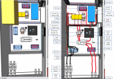
So whadda ya do when you're bored stiff, isolating and STILL waiting for cells to arrive??

(Click pic in this link for higher rez image.)

Big yellow box in upper left (left-hand pic) is my inverter. Hid it in the pic on the right to show wiring. Think I need a 2nd NEG bus. That one on the right's pretty crowded so I added a 2nd one the left pic that I'll connect to the one on the bottom and move some of those wires to it.

1590373545267.png
 
Last edited:
So whadda ya do when you're bored stiff, isolating and STILL waiting for cells to arrive??

(Click pic in this link for higher rez image.)

It looks like the Inverter is being fed by a +ve cable from your 24V-12V but I think it's just the tangle of cables at that point above your load breakers.
 
... What does the GFP provide? Without one where I have it now, shorts (to GRND or NEG) along A>B might blow the DC Fuse or maybe trip the 80A breaker (even though it's polarized to work in the opposite direction) but there's a lot of wire involved in that short. [Omitted the 3-30A breakers cuz they're kinda redundant for the purposes of this discussion.]

View attachment 13663

With the GFP solution (.5A breaker ganged with 80A breaker) ...

View attachment 13662

... those shorts will always trip my 80A breaker and will do so very quickly. Battery, Panels and DSSRs are much less involved and virtually no surge. Any potential between GRND and NEG and that .5A breaker will instantly trip and open the 80A one when it does. Rated at only .5A, I think it would probably even trip for a double fault.

PV GFPs like this are actually required for NEC compliance. What that particular breaker does in my design is a little more complicated but you can immerse yourself in all the gory details here. ;)

I don't see what the second arrangement with the 'ground-fault' breaker gains: in scenario 1 (traditional, chassis tied to NEG) a fault in the A-B circuit to either chassis or PV panel negative would draw a large fault current from your POS bus (sourced by the battery), that would open the 80A breaker (or the smaller per-panel breakers omitted in this diagram) before the smoke gets released. (BTW, that breaker, if polarised, should be reversed with the '+' side connected to the POS bus; ref. the very last paragraph on p2. of the midnitesolar doc you referenced.) In scenario 2, the smaller 0.5A "ground-fault" breaker may - or may not - open more quickly, and thus force the coupled 80A breaker to open, but you'd have to compare the response characteristics to be sure; I suspect it'd be invalid to assume a smaller breaker would physically respond more quickly than a larger rated one (the current ratings are, for similarly "sized" breakers, just a matter of the number of windings on the internal electromagnet).

AIUI, the motivation for ground-fault interruption on fixed installations is more to do with fixed installs usually running large numbers of panels in series, on the order of 1kV. Those conditions can certainly raise personal safety and fire concerns, and it makes complete sense to use a ground-fault detection mechanism to isolate the PV array when unexpected earth current flows. i.e. the PV itself is the danger. With a vehicle system's low voltage, and much lower power PV array, the PV array is not a danger to anything (the panels can't exceed the wiring capacity, and your design correctly has breakers per panel at the junction). The source of danger here is simply from the battery. The 80A breaker does the job on that front.

I'm working on a similar design, so very happy to be shown otherwise!
 
(BTW, that breaker, if polarised, should be reversed with the '+' side connected to the POS bus; ref. the very last paragraph on p2. of the midnitesolar doc you referenced.)
Yeah, I'll need to confirm if the 80A side of that breaker is polarized or not. Product spec on MS site:
1590578951488.png
... yet, pointing me back to that doc and the statement MS makes about ALL their DC brkrs being polarized led me to look at the actual breaker I got. Sure enough, terminals are indicated Line and Load so I'd need to swap top and bottom connections in my diagram. I'll call 'em to confirm, but NICE CATCH if true! (y) Would kinda suck though cuz that's just makes cable runs a little more cramped w config above so I'd probably rearrange things down there to better accommodate the new wire run for the GFP. Was thinking of doing that anyway cuz I'd prefer not to have one shunt directly above the other as they can get pretty hot.
I don't see what the second arrangement with the 'ground-fault' breaker gains: in scenario 1 (traditional, chassis tied to NEG) a fault in the A-B circuit to either chassis or PV panel negative would draw a large fault current from your POS bus (sourced by the battery), that would open the 80A breaker (or the smaller per-panel breakers omitted in this diagram) before the smoke gets released.
In scenario 2, the smaller 0.5A "ground-fault" breaker may - or may not - open more quickly, and thus force the coupled 80A breaker to open, but you'd have to compare the response characteristics to be sure; I suspect it'd be invalid to assume a smaller breaker would physically respond more quickly than a larger rated one (the current ratings are, for similarly "sized" breakers, just a matter of the number of windings on the internal electromagnet).
AIUI, the motivation for ground-fault interruption on fixed installations is more to do with fixed installs usually running large numbers of panels in series, on the order of 1kV. Those conditions can certainly raise personal safety and fire concerns, and it makes complete sense to use a ground-fault detection mechanism to isolate the PV array when unexpected earth current flows. i.e. the PV itself is the danger. With a vehicle system's low voltage, and much lower power PV array, the PV array is not a danger to anything (the panels can't exceed the wiring capacity, and your design correctly has breakers per panel at the junction). The source of danger here is simply from the battery. The 80A breaker does the job on that front.
Yeah, it may be unnecessary for the SIZE of my system but, TBH, this rig traverses some pretty rough terrain on a regular basis and harsh climates (esp winter ones) and I've tried to build in redundant safety solutions where I can and additional safeguards that might not be entirely needed but cost/benefit is so low that it's hard to justify NOT doing it e.g. inverter pre-charge to keep switch and breakers from degrading.

I also kinda view the entire living quarters where this closet is located like a bathroom where GFCIs are required for protection in wet/steamy conditions (this is a really interesting history of GFCI btw, and the Effects of Electricity section was an especially compelling rationale for starting to head down the GFP path in my design).

I especially like the back up the GFP provides on top of the normal breakers (BTW, those 30A breakers are polarized and designed to trip for OC from panels, not OC from battery). I understand your breaker winding argument but I have to think that that .5A breaker will trip LONG before any of the others would given the MUCH lower A threshold and the MUCH shorter wire length involved.

Side benefit, too: ground wires for those GFP-protected products can be much smaller. In my diagram above, Inverter and 12V DC GND wires to NEG are #10. I could go as small as #22 if they were on a GFP breaker.

Here's the funny thing too, I think that PV GFP would trip if anything on my load side is leaking or shorting. It wouldn't stop that leak, but would make it MUCH easier to troubleshoot what's causing it simply by disconnecting individual DC appliances until that GFP stops tripping.

So, I'm not an electrician but I THINK I understand how all this works and can kinda see why the NEC requires it in residential settings. While this residence is small in comparison maybe to what they had in mind, it's STILL a residence. ;)
 
I am also dissapointed by this. I would clarify though, that its not that you can't put it on the positive side, its just that you can't put it on the positive side between the battery and the shunts

I brought this up to Dacian in an e-mail:
...
DACIAN "ElectroDacus" said:
The option B is what I recommend in the user manual. The current shunts will be very close to the battery is not even inside the battery box so it can be considered a panel installation it will be impossible to make a short circuit before or on the current shunts as there will be no negative path anywhere close to that any short can happen just after the circuit breakers or fuses. For extra protection you can add a much large value fuse on the negative side just after the negative battery terminal.
...
My reservations weren't completely assuaged by his answer, but I do think its a smaller risk than I first felt it was if properly designed.
After our discussion on the other grounding thread, I was re-reading this thread and saw this. I don't understand that, seems like if solar was charging then blowing a negative terminal fuse could result in higher voltage solar connected to lower voltage loads without a battery, resulting in damage. Edit: Of course that would be true for a positive disconnect as well, unless there was some other mitigation.

Looking at the SBMS0 schematic, I also don't understand why it would be damaged if there was a positive disconnect or fuse before the shunts. The current sense amplifiers can take up to 76V common mode and the sense inputs can be above the amplifier power supply, they are completely independent. So not clear to me why it would be damaged.

I've emailed him about both of those, will report back.
 
  • Like
Reactions: Dzl
I've asked Dacian the question in regard to disconnects or fuses upstream of the shunt... it is in fact the instantaneous power potential across the shunt. I thougt it might be addressed in the same manner as inductive flyback using a diode, but evidentily not so.

Here's what he replies when I raised the question in the thread that precipitated this dialog:

"No a diode or even two across the current shunt will not help as that is not the problem. both side of the current shunt will be a negative voltage that means current shunt when mesured as reference to GND (battery negative terminal) will be negative say -100V. As there is a diode inside the current shunt amplifier between current shunt sense and GND that diode will try to clamp the inductive pulse created by disconnecting the current but if that energy is two high it will not be able to and the internal diode will fail resulting in a damaged current shunt amplifier.
If is just 1 or 2 A when shunt is removed from battery+ then internal diode my be able to clamp this small energy pulse but if say 1kA or even 10kA is what is disconnected fairly possible if you have a fuse that fails and is incorrect placed between battery+ and current shunt and not after shunt."
 
Back
Top