diy solar

diy solar

Electrodacus Design-Adding Alternator and Inverter/Charger

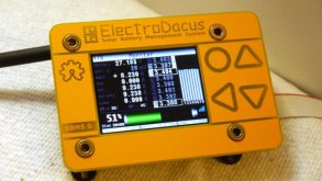
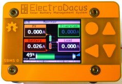
This is what one of the 6 monitoring screens on the new version of the SBMS looks like.
PV = Chargers
Load = Loads
Battery = Battery
Diversion = optional SBMS specific feature to divert excess energy to other purposes, most notably heating. There is not yet a built in ability to measure diversion current.
P1300405.jpg


Another of the monitoring screens:
Front-GBS.jpg

*PV2 is a holdover from older models, I don't beleive it is actively used on this model (might be mistaken though).


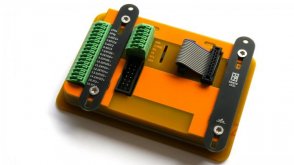
Rear connectors:
1604967152112.jpeg
 
Last edited:
Great explanation, one day I'm going to take the time to stare at your schematics long enough for it to completely

penetrate my dense skull and read your planning or build thread (if you have one), you've got a lot of good and creative ideas and knowledge (though I still think you have chassis and earth ground symbols confused ;)).


If by deal with you mean accomodate and monitor, then yes. But you don't have the granularity of seeing how much each source is contributing. You will see overall charge current and total net current. So yes, you could measure all three of those charge sources in aggregate, not individually.

But as I alluded to above, the big caveat is an inverter-charger. because it only has one set of wires for inverting and charging, net current will still be accurate (so it will still work as well as a battery monitor) but individual charge and discharge readings will be skewed. This is a shortcoming but the SBMS was designed for an off-grid context where there is no shorepower. One solution is to just use a separate inverter and charger, and the SBMS0 is designed to work with cheap and simple meanwell style power supplies (since control/logic resides with the BMS) or traditional battery chargers.


All loads will be measured in aggregate, so you can add as many differences loads as desired and it will measure them accurately without additional components, but you will not have the granularity of being able to see current for specific loads.

One more consideration is that Victorn products and the electrodacus dovetail quite nicely. While they don't communicate they do work quite well together and the SBMS can control most Victron equipment, so for those of us obsessed with data and micro managing and customizing, the marriage of the two is appealing (though there are a lot of redundancies in that case).

What specifically do you mean by "would you be able to do the kinds of things I am doing?"
One example is preferential load shedding at different levels of battery SOC. That requires multiple low voltage disconnects, each triggering at different threshold voltages. I am sure I could have managed that from a central point using a Venus GX, but I implemented that instead by distributing the low voltage shutdown function across multiple devices.
  • AC (Multiplus) loads turn off first.
  • 12VDC loads turns off next.
  • 24VDC loads turn off last.
I never mentioned this before, because that capability was implicit in how I organized my system. That capability was built into the system by design, not accident.

Cold Temperature charge disconnect is controlled by a single device. The BMV-712. This has two mechanisms.
  • SmartSolar by VictronConnect over BlueTooth
  • Orion-TR and Multiplus by contact closure input.
I wish Victron would add VictronConnect control to the Orion-TR and Multiplus, but I am not holding my breath waiting for it.

I want to have coordinated charge rate control so I can define the maximum charge rate I want the system to use and have the various charge sources negotiate how to this. I could do this with a Venus GX, but instead I will just set the Multiplus max charge to a level that even combined with max solar power I stay under that limit. I am not worried about alternator and solar together (that will be less than the Multiplus alone) and alternator plus multiplus charging is not likely to happen, since I don't have a long enough extension cord to do both at the same time (joke).

Obviously I want to be able to geek out and see each charge sources contribution and power consumption in real time, but that is just the giddy kid inside of me. The above features are what I think I actually need. I am going to have all of that.

I would love to be able to control all charge and discharge limits using the BMV-712 SOC measurement, but that would definitely require a GX device to orchestrate everything and a lot more head scratching on my part. I am not convinced the refinement in control will really gain me that much.
 
Obviously I want to be able to geek out and see each charge sources contribution and power consumption in real time, but that is just the giddy kid inside of me. The above features are what I think I actually need. I am going to have all of that.
I can relate ?

One example is preferential load shedding at different levels of battery SOC.
Yes. In fact I can see two ways to accomplish this decentralized or centrally.

Decentralized is basically how you have it setup, multiple LVD's + Inverter LVD can be programmed how you see fit. In my now-temporarily-abandoned early alpha design, I had roughly the same 'load shedding' logic as you. See here achieved through a combination of SBMS and Victron features.

Centralized: the SBMS has 4 EXTIO ports that can be used however you want. The default configuration is EXTIO 3 & 4 are used for chargers and loads, and 5 & 6 are not used. But they can be used creatively.

You could use them for load shedding, or flexibly managing chargers, or for redundant layered protection, or whatever you can think to do really.

Some combination of the two approaches could be combined.

Cold Temperature charge disconnect is controlled by a single device. The BMV-712. This has two mechanisms.
  • SmartSolar by VictronConnect over BlueTooth
  • Orion-TR and Multiplus by contact closure input.
Yes the SBMS would centrally control low temp cutoff for all charge sources.


I wish Victron would add VictronConnect control to the Orion-TR and Multiplus, but I am not holding my breath waiting for it.
Me to

I want to have coordinated charge rate control so I can define the maximum charge rate
This would be nice, A Samlex Inverter/Charger or a Victron GX device (including raspberry pi running VenusOS) are two ways to accomplish this.

The low tech solution is to size everything so that 2 of 3 charge sources are less than whatever you want your max C rate to be, and 1 of 3 (or at least your primary source) is enough to refill what you use in an average day.

The diversion feature of the SBMS or the unused PV1 / PV2 functionality might be of some use here, but im not positive. The thing with the SBMS is there is a lot of flexibility, it allows you to get creative but its not always easy to imagine what all is possible, and some features aren't 'exposed' or obvious in the software or the hardware but are technically there (the new version exposes many of them)
 

Attachments

  • dzl_mobile_system_working_draft_1.png
    dzl_mobile_system_working_draft_1.png
    215.8 KB · Views: 54
I can relate ?


Yes. In fact I can see two ways to accomplish this decentralized or centrally.

Decentralized is basically how you have it setup, multiple LVD's + Inverter LVD can be programmed how you see fit. In my now-temporarily-abandoned early alpha design, I had roughly the same 'load shedding' logic as you. See here achieved through a combination of SBMS and Victron features.

Centralized: the SBMS has 4 EXTIO ports that can be used however you want. The default configuration is EXTIO 3 & 4 are used for chargers and loads, and 5 & 6 are not used. But they can be used creatively.

You could use them for load shedding, or flexibly managing chargers, or for redundant layered protection, or whatever you can think to do really.

Some combination of the two approaches could be combined.


Yes the SBMS would centrally control low temp cutoff for all charge sources.


Me to


This would be nice, A Samlex Inverter/Charger or a Victron GX device (including raspberry pi running VenusOS) are two ways to accomplish this.

The low tech solution is to size everything so that 2 of 3 charge sources are less than whatever you want your max C rate to be, and 1 of 3 (or at least your primary source) is enough to refill what you use in an average day.

The diversion feature of the SBMS or the unused PV1 / PV2 functionality might be of some use here, but im not positive. The thing with the SBMS is there is a lot of flexibility, it allows you to get creative but its not always easy to imagine what all is possible, and some features aren't 'exposed' or obvious in the software or the hardware but are technically there (the new version exposes many of them)
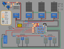
I don't see how the Electrodacus manages load shedding here. I don't see any control line coming from the Electrodacus to the switched loads.

What is the difference between switched and unswitched loads?
 
I don't see how the Electrodacus manages load shedding here. I don't see any control line coming from the Electrodacus to the switched loads.
In my diagram it doesn't. I chose the decentralized approach (actually at the time, I didn't know there was a way to do it at the BMS). The Victron Smart Battery Protects would be programmed to cutoff at different voltages, and the inverter could as well. All would be controlled by the BMS, but the BMS would only step in as the last line of defense in that iteration of my design.

But with the centralized approach you have up to 4 independently controllable control lines at your disposal (EXTIO 3-6). This is the best part of the the new model, prior to the upgrade only two EXTIOs could be used without soldering and an addon board, now all 4 can be used out of the box. Each of these can be programmed to respond to some trigger, and to control some load control device or charge device (or grouping).

The SBMS can control most Victron devices, external relays, battery protects, and so on.

What is the difference between switched and unswitched loads?
I borrowed the term from a video I watched on marine electrical system design, the term didn't perfectly translate to my design, but I kept it since I couldn't think of anything better at the time.

In the system I borrowed it from, it basically referred to 'always-on' essential loads (nav, comms, fridge, etc), and non-essential loads.
If I were to redraw the diagram which I will at some point if I pick that project up again, I would use different terminology, but the basic premise was to have two tiers of loads (3 if you count the inverter) which would be switched on/off at different voltages or states of charge. I think this is essentially what you are referring to as 'load shedding'
 
In my diagram it doesn't. I chose the decentralized approach (actually at the time, I didn't know there was a way to do it at the BMS). The Victron Smart Battery Protects would be programmed to cutoff at different voltages, and the inverter could as well. All would be controlled by the BMS, but the BMS would only step in as the last line of defense in that iteration of my design.

But with the centralized approach you have up to 4 independently controllable control lines at your disposal (EXTIO 3-6). This is the best part of the the new model, prior to the upgrade only two EXTIOs could be used without soldering and an addon board, now all 4 can be used out of the box. Each of these can be programmed to respond to some trigger, and to control some load control device or charge device (or grouping).

The SBMS can control most Victron devices, external relays, battery protects, and so on.


I borrowed the term from a video I watched on marine electrical system design, the term didn't perfectly translate to my design, but I kept it since I couldn't think of anything better at the time.

In the system I borrowed it from, it basically referred to 'always-on' essential loads (nav, comms, fridge, etc), and non-essential loads.
If I were to redraw the diagram which I will at some point if I pick that project up again, I would use different terminology, but the basic premise was to have two tiers of loads (3 if you count the inverter) which would be switched on/off at different voltages or states of charge. I think this is essentially what you are referring to as 'load shedding'
Exactly the same. In fact my 12V loads have to be manually reconnected by pressing a push button. That way these won't turn themselves back on if the low voltage disconnect triggers.

The 24V loads will automatically reconnect when the battery voltage recovers.

That is why the 24V loads are powered from the Smart Solar load output and the 12V loads are powered by my homebrew circuit.
 
  • Like
Reactions: Dzl
If I understand the question--electrically I would think it would probably be the same either way, but I'm not positive. Physically, I'm not sure.
Are these all in series? I am not sure what you are doing.

If talking load, then as long as each load is wired to independently then it doesn't matter. The reasons to use a busbar are to make the wiring neater and more logical. Plus it helps remove the temptation to wire power in a daisy chain fashion (from Load A to Load B to ...).

Think of the image of a starfish or an octopus with all the positives leads coming from a central point and all the negative leads coming back to a central point. Making those central points busbars makes it easy to terminate a lot of different wires to the same point. You can only stack so many ring terminals under a single screw.
 
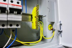
Here is an example of individual device chassis grounds being terminated inside an electrical control box. Those yellow with green stripe wires are all individually connected to the enclosure chassis ground via a single wire from the busbar to the enclosure ground stud. That is different from wiring a single ground wire to the first device, then running a ground wire from the first device to the second device etc, which would be an example of daisy chain wiring (something I strongly disagree with doing).

Electrical-wires-grounding-bar-breaker-box.jpg

Note the above image must not be from North America. The standard here is that the protective earth wire is bare copper (preferred) or insulated with Green or Green with a Yellow stripe.

 
DZL said:
If I understand the question--electrically I would think it would probably be the same either way, but I'm not positive. Physically, I'm not sure.
Are these all in series? I am not sure what you are doing.
Did you quote the right thing? I don't understand the question in the context of the quote.

If I were to guess at what you are referring to, I suspect maybe the PV and MPPT grounding conductors in my schematic?
If so, they are sorta placeholders, I'm not 100% sure how they would eventually be wired, what I chose for the schematic was to primarily show they would be grounded in some way shape or form, and declutter an already cluttered schematic. In practice the charge controllers would each have their own grounding conductor run to the busbar, not sure about the PV panels, I'm still not 100% sure how necessary discrete grounding conductors are in a mobile context (where the PV panel frames are bonded to the vehicle body in most cases).

If talking load, then as long as each load is wired to independently then it doesn't matter. The reasons to use a busbar are to make the wiring neater and more logical. Plus it helps remove the temptation to wire power in a daisy chain fashion (from Load A to Load B to ...).

Think of the image of a starfish or an octopus with all the positives leads coming from a central point and all the negative leads coming back to a central point. Making those central points busbars makes it easy to terminate a lot of different wires to the same point. You can only stack so many ring terminals under a single screw.
(y)
 
Moving the "ungrounded ground" discussion to my system drawing thread located here:
Did you quote the right thing? I don't understand the question in the context of the quote.

If I were to guess at what you are referring to, I suspect maybe the PV and MPPT grounding conductors in my schematic?
If so, they are sorta placeholders, I'm not 100% sure how they would eventually be wired, what I chose for the schematic was to primarily show they would be grounded in some way shape or form, and declutter an already cluttered schematic. In practice the charge controllers would each have their own grounding conductor run to the busbar, not sure about the PV panels, I'm still not 100% sure how necessary discrete grounding conductors are in a mobile context (where the PV panel frames are bonded to the vehicle body in most cases).


(y)
Wrong quote.
 
  • Like
Reactions: Dzl
What specific types of information are you looking for?

Victron Wiring Unlimited is the closest thing to an intermediate level comprehensive book that I am aware of. But I have loooots of specific recommendations depending on what you are looking to learn about. Sometimes I feel a bit like the forum librarian :) I'm not the smartest, most knowledgeable, or most experienced here, not by a long shot, but I'm pretty good at finding information, and have developed a pretty decent breadth of knowledge, so I like helping match people up with the info they seek (particularly because often they can understand it deeper than I have, and teach me something new)

If you look in the resources section of the forum, I have added a lot of the resources that I lean heavily on, FilterGuy Also has some great resources.

I also have a thread where I organize the resources I have found useful, though most of the resources are from much earlier in my learning process

Of note are:
  1. Victron Wiring Unlimited
  2. ABYC marine electrical code (this is the most DIY friendly code I have found)
  3. The Magnum and Samlex Inverter Manuals (I don't own either but I use both documents as references, specifically for grounding related questions)
  4. The near-comprehensive introductory articles on LFP in my signature from Nordkyn and Marinehowto (and the shorter article by Solacity)
  5. Videos by Pacific Yacht Systems for general marine electrical design and AltE store solar information at the beginner to intermediate level
  6. This video on circuit protection as well as this powerpoint
  7. A great video explaining the basics of electricity on a conceptual level, this video is what made a lot of things finally 'click' for me
  8. RSD Academy videos and articles on grounding and voltage (among other topics)
  9. Videos or Articles by Mike Holt on grounding etc, in the context of the NEC

But based on what you are looking to learn I might have other recommendations.
Gold mine of resources for newbies like myself!

This statement from Nordkyn Design on charging LiFePO4 concerns me:

"Charging must stop when the absorption current falls below the termination current threshold, because this means that the cells ability to absorb current has reduced down to the point where the cells must be considered to be full. Any further charging constitutes overcharging and leads to a point where the cell completely runs out of free lithium and no current can flow any more. Therefore the battery current is a critical piece of information and it must be known and used to control charging."

This would be a nice feature to add to the SMBS0 firmware.
 
My opinion is that DC systems should be completely isolated from vehicle (chassis) ground except at a single point where the system negative is connected to chassis ground. In my further opinion, the best power and ground distribution scheme is a star where every DC load has a dedicated positive and negative wire that feeds back to a central positive and negative bus bar. The battery is connected to the positive and negative bus bars with dedicated wires. In this case the negative bus bar is what should be connected to chassis ground.

That may be your opinion, but that's not how vehicle power distribution is done. My vehicle is typical. It utilizes chassis to carry current. There are at least 7 chassis bonding points to access battery power at various locations in my RV. My battery negative cable connects to a shunt and then goes directly to chassis. There are no ground loops. This saves a ton of cable. The positive cable is all that requires routing. And... resistance through the chassis is almost always less than cable.
 
. Lower current devices grounded at chassis should not be a problem but a 300amp inverter might create a differential across even a chassis. Usually Ive seen the vehicle battery grounded either at the engine or via a heavy short ground strap close to battery ground point. For my house system there will be some distributed 24v for lighting and local power points (mini dc-dc 12v /usb) and those will probably use localized chassis ground points. But inverters and such will connect to the primary ground/power points.
 
What cable do you suggest for a 300A inverter? I would say there's something wrong with the design if a 300A inverter is required. A more reasonable approach would be to double the battery voltage and half the current.

Due to high currents and the resulting voltage drop, the inverter is located extremely close to the battery. Therefore it makes no sense to utilize the chassis as a ground return.

The difference in conductivity of iron and copper is a factor of 7. If the cross section area of the chassis is more than 7 times the cross section area of the cable then the chassis will have lower resistance.
 
Right, large current draws should never be run through the chassis but back to the common battery ground point. In my case 0.5C will be 270amps@24v which is exactly what the alternators output is. The vehicle battery is first grounded at the starter case then a fat cable runs to the aluminum chassis. The alternator output connects to starter battery cable. So all those high currents are never seen by the chassis.

Thinking about how to integrate the house battery bank so high currents are not seen by chassis.
 
large current draws should never be run through the chassis ...

What do you base that on?

I haven't seen any automotive alternator that doesn't use chassis as a conductor. It is an industry standard to use chassis as a conductor. Doesn't matter if it's 2A or 200A; as long as the chassis is designed to carry that current.

 
Last edited:
For one my coach's starter has two cables power and ground directly to the starter batteries. The 270amp alternator connects directly to the positive cable at the starter. The starter ground point has a short heavy strap to the chassis. Later coaches ran a complete separate ground cable from starter ground the front of the coach where high current grounds were collected and attached at that junction. No doubt a move to improve reliability and performance as chassis grounds tended to suffer dissimilar metal corrosion after a few years in operation.

My 2001 jeep cherokee battery negative terminal has a small ground to chassis and big one directly to engine block starter side. For positive it has small cable to power junction (alternator connects there too) and large cable to starter.

To me the theme is the same for both. High currents are supplied via direct cables.

Modern cars with computer engine control updated grounding so starter current is fed directly from battery with both power and ground cables to engine/starter.
 
I attached diagram so it would be clearer but that what I'm thinking
Hi, it's been awhile-Covid! I have been rethinking my system that all you have been so nice to review-Thank You! I'm considering or rethinking a couple of items.

1. MRBF fuse is that what it needs to be for 24v 280ah Lifepo4 battery and 3000 watt 24v inverter? Or should I be using a 250a class t fuse or is the MRBF acceptable??

2. Should I add a double pole breaker between solar panels and DSSR20s so that I can isolate solar panels??
3. Is the use of the 50a and 60a breaker in green going to 12 and 24v DC fuse blocks and before pv shunt in attached acceptable or should I consider fuses??
 

Attachments

  • Electrodacus Solar Electrical Diagram XII (2).pdf
    267.5 KB · Views: 4
Back
Top