diy solar

diy solar

Electrodacus SBMS40 3D Brothers Edition Review Thread

Sverige

A Brit in Sweden
Joined
Oct 8, 2020
Messages
743
Location
59.5N, 15.5E
I’ve received one of the new “3D brothers edition” Electrodacus SBMS40s from the prototype batch, as offered forum members for review purposes recently by Alex Gradea. It’s not clear to me right now what, if any changes might feature in the production batch of units, so for now I’m assuming this is how the units will ship to customers who ordered via the recent indiegogo crowdfunding campaign.

What is an SBMS40? It’s a combined smart BMS and solar charge controller capable of managing up to 8S configs of lithium cells while allowing connection to the battery of PV panels (at battery voltage) up to 40A of current, subject to the unit being mounted on a suitable heatsink to dissipate 8W of thermal energy. Full specs are listed in the excellent PDF manual provided by Dacian Todea, the creator of the Electrodacus range. The BMS has a wifi module and allows remote connection to PC, smartphone or tablet for remote monitoring.

What is the “3D brothers edition”? Well this is Dacian Todea’s electrical design redesigned for mass production by the 3D Brothers company. The software and therefore user interface is identical to the original Electrodacus product, only the physical form has changed. The most obvious differences I can see are that the PV, battery and load cables solder direct to the board rather than being retained in screw down terminals and the aesthetics are different as the boards are green rather than Dacian’s original yellow version. I understand the SBMS40 is a currently discontinued product by Dacian, so for now this will be the only version people can buy.

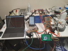
This thread will grow over time as I make use of the unit in my off grid solar setup and I’ll add to it as I go. Here in Sweden during December there’s about as much sunlight as inside a closed refrigerator and the temperature is even lower, so it may be some time before I use the full capability, but I think there’s value in me making posts to this thread each time I learn more about the unit and I’d like to cover topics like wiring, setup, remote monitoring, power consumption, system integration with other components like additional charge controllers, inverter, etc.

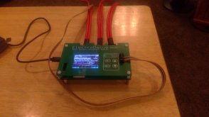
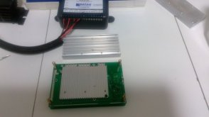
I thought a good place to start is with some photos of the unit, as one thing I found hard when planning how I might make use of this unit was that I didn’t find any clear photos of how the boards looked. The front panel is removeable and may be mounted remote from the main board, subject to the ribbon cable being extended. I’ll aim to discover what distance limits apply and also how (whether) the main board runs without the front panel connected at all.

17EB09AE-779F-4FD0-8A7E-95E250007D27.jpeg606B6013-CFE7-40EC-A8CC-7E8E8422BBB5.jpeg21F4326C-4B35-4B04-85F4-407736343F7C.jpeg76CD95E8-2479-474F-97ED-88022450D8B1.jpeg02A5463F-AEA9-43D0-9A50-D9C3660CD50B.jpeg6B73281C-EE27-4F5D-8B69-461DE3BAC295.jpeg499D25DE-C200-4C52-ACF1-EBCA0CA4AF39.jpegEAF9B4AC-2C55-4932-9EBC-14B59142003E.jpeg\

Conclusion:
 
Last edited by a moderator:
Just to add, by the way, I’d like this thread to be open for others who get one of these units to add their impressions or reviews. It’ll be more helpful to other users in the future if info on this version of the Electrodacus board is contained within one thread than if there are several.
 
  • Like
Reactions: Dzl
Connections to this unit are made via the header connector for individual cell balance voltages, and three solder pads towards the bottom of the main board, one for PV panel input, the second for a connection to battery positive and the third for load.

With 3.7mm dia holes and 4 holes for the first two connections and two holes for the load connection, there’s plenty of space to connect multiple wires and split the current load over more than one cable. I will probably use multiple 4sqmm (12Awg) wires, as 4 of those parallelled up is plenty for a 40A Max load, and soldering thicker wires to this board might need so much heat from the soldering iron that the surface mount components close to the solder pads might suffer. I suppose it’s possible that on the production release of this device, 3D Brothers may fit clamp type connectors to accept the cables.
7E30182D-502A-4377-836E-50CBF4E467AD.jpeg
ADD3F4D9-73F3-4AB4-873D-B5DDDF31F068.jpeg D4B7D300-0A41-4A7F-85E6-FF2BD01D6B9F.jpeg B78205EC-94BE-46B5-89FB-4B522CC7C6E7.jpeg
 
I would like to thank Alex Gradea of DeepCycle-Power for sending a prototype version of their "Green" SBMS40. As Sverige did an excellent job of photo shooting the unit I won't.
The first thing I did was to hook up USB power to have a look at the software. It is clearly the same as Dacian's Manual shows. One concern I have is the manual state that -if over 30 amps it will need a heatsink or fan- The first test will be at 31 amps max using my Bogart SC2030 charge controller as a DC to DC charger to mimic solar charging. The SBMS40 will control an SSR on the AC side of the power supply for charging. On the discharge side, I will control the load side through an SSR using halogen bulbs at about 32 amps. I plan on using a temp controller and fan as a temp back up. What temp should I set the fan to come on? Any thoughts or ideas? Thanks.
I guess once the fan switches on, it will limit the temp rise. So it’s no problem if the fan kicks in sooner than strictly needed. I’d probably set it low myself, maybe 30C? I would have thought that as long as the main board stays below 40-45C it will be happy.

I have a nice big heatsink to mount mine on, but hadn’t realised the back of the board would have exposed PCB pads and traces*, so I’ll need to order in a heat conductive thermal pad of the right size before running significant current thru it.

I’ve heard from Alex that the only changes in the production batch will be a small rearrangement of the front panel and changes to the printing. The main board will be as supplied on these test units.

*I know I really should have realised this!
 
Last edited:
The WiFi works with no effort to speak of, as does the App Dacian has in his manual.
 
I'm using a ESP32 to get bms data on a tablet. Since Electrodacus is open source, is his WiFi code listed somewhere? I got some crude html code working, but would be great to see a finished product.
 
I'm using a ESP32 to get bms data on a tablet. Since Electrodacus is open source, is his WiFi code listed somewhere? I got some crude html code working, but would be great to see a finished product.
I may be wrong, but I don’t believe the software source code has been published
 
  • Like
Reactions: Cal
I’ve been in touch with Alex from 3D brothers today, who tells me they are developing a heatsink for the SBMS40 to be sold as an optional item, which is good news. Also that the unit includes an additional FET compared to Dacian’s original design, so as to spread the charging current across more devices and limit thermal stress on each FET.

My other observation would be that the physical design of this unit, with two boards spaced apart and no sides, means it should lend itself to passive convective cooling when vertically mounted. Since the PV string I plan to use it with should peak at around 22A, and my ambient temperature is under 20C, I’m planning to begin using it without a heatsink and just monitor temperatures.
 
I'm using a ESP32 to get bms data on a tablet. Since Electrodacus is open source, is his WiFi code listed somewhere? I got some crude html code working, but would be great to see a finished product.
This will likely help Cal ESP32 Forum
 
  • Like
Reactions: Cal
I’ve been in touch with Alex from 3D brothers today, who tells me they are developing a heatsink for the SBMS40 to be sold as an optional item, which is good news. Also that the unit includes an additional FET compared to Dacian’s original design, so as to spread the charging current across more devices and limit thermal stress on each FET.

My other observation would be that the physical design of this unit, with two boards spaced apart and no sides, means it should lend itself to passive convective cooling when vertically mounted. Since the PV string I plan to use it with should peak at around 22A, and my ambient temperature is under 20C, I’m planning to begin using it without a heatsink and just monitor temperatures.
According to the manual, It dos not require a heat-sink at 30amps charge and discharge. But it would be prudent to heat-sink anyways. And I agree with the open design will assist with heat convection transfer. I have added stand-offs and the heat-sink from the BMS8T will deal with the 8 watt's of heat. ( perhaps less with the added FET and open design )
 

Attachments

  • WIN_20201214_11_48_56_Pro.jpg
    WIN_20201214_11_48_56_Pro.jpg
    31 KB · Views: 31
According to the manual, It dos not require a heat-sink at 30amps charge and discharge. But it would be prudent to heat-sink anyways. And I agree with the open design will assist with heat convection transfer. I have added stand-offs and the heat-sink from the BMS8T will deal with the 8 watt's of heat. ( perhaps less with the added FET and open design )
Nice solution (y)
 
With wiring harnesses attached for the PV, Battery and Load connections, plus an improvised multiway lead for the individual cell voltages, I’m ready to install this. Only when I approached my power wall with the thing in my hand did I realise, I don’t know how I’m going to screw this to the wall! There are holes in the back PCB, but I’m not sure they’re intended for mounting, and the four corner holes are occupied with the plastic stand offs.

Probably I’ll have to remove the standoffs and go thru those holes with a long self tapping screw, straight into the wall behind and make use of some spacers to hold the two boards apart. If anyone has a better idea please shout! 26429597-FF0A-488A-9EC2-F31ED74F43E6.jpeg
 
The stand-offs are 4mm. Figure out how thick and buy screws.
My 2x5 connectors showed up. So here is where I'm at.
 

Attachments

  • WIN_20201218_19_22_18_Pro.jpg
    WIN_20201218_19_22_18_Pro.jpg
    40.9 KB · Views: 55
Thanks @grizzzman, I agree the standoffs are the solution. I’ve swapped the short 10mm M3 plastic stand-offs which seperated the boards for 20mm ones and added 15mm stand-offs to the back side. Now I can add an oversized backing board so I can screw directly to the wall surface. With more space either side of the main board, an added benefit should be better airflow and lower temps if I start pushing the PV charging current harder.

I’ll suggest to Alex that a future improvement to his design might be to oversize the rear board widthways and have mounting holes on each side, in similar positions to the discontinued Dacian version of the SBMS40. I imagine most people buying these will want to mount them onto a flat surface.

I’ve also suggested fitting the board with captive screw connectors at the factory stage, as I didn’t find it very easy to solder the thick cables to the board. They need a lot of heat, because the cable sucks the heat away, and the FETs and other surface mount devices are kind of close to that area. It‘s certainly do-able, but something people with less experience of soldering (or anyone with a lower power soldering iron) might find awkward.

CC4B21D6-29D1-4486-A1E5-AA4F4C6476F8.jpeg
D4C58AB3-0500-47AA-9D98-75B52BF91078.jpeg
 
I went ahead and connected the SBMS40 to my 4S LiFePO4 pack, following the sequence in Dacian’s manual.

1) First Batt+ (thick cable) to battery positive
2) Then individual cell connections via 2x5 pin header connector
3) Then set battery type and number of cells in the ”parameter settings” menu and use “store parameters” option
4) Finally remove the header connector and reconnect

Ok, I admit, I deviated from this a little and maybe paid the price, as upon rebooting I saw that yes, the change to 4S had taken and yes, my cell voltages were being monitored nicely and showing voltages within 1mV of each other, but....

The third page of the monitor screen was lit up like a Christmas tree with all sorts of flags, Over Voltage, Under Voltage, Cell Fail, Open Cell, etc...

What did I get wrong? Instead or removing the 10pin header connection completely, I had just lifted the negative connections at the battery end (pins 1&2 of the header connector), in order to reboot the device. I reasoned that this was all that unplugging the 10 pin connector was meant to achieve, but seems like somehow I caused an issue. After unplugging the 2x5 pin connector fully and connecting it again, things seem happy and I can proceed with the final install step (prior to connecting PV and Load cables), which is:

5) Hold down OK on monitor screen and select “Load off” to disconnect the FET which couples the load output.

69502D52-F68C-4F2C-ADEA-840967745882.jpeg65DB6966-78FD-44E0-855F-934749563234.jpeg
 
I’m seeing some phantom current on PV and Battery display, and not sure why. PV not even connected at this stage ?‍♂️

965256E1-1BBA-420A-BF51-E5824586A8C1.jpeg
 
So my low tech solution to mounting is a rough cut scrap of 3mm fibreboard which I can screw thru into the wall behind. It will also help with cable strain relief as I can cable tie the CAT6 cable to the back board when the time comes to connect to the automation port on the lower edge of the unit.

Some minimal PV power here today, so I have it charging my battery with a scant amp or two and a few DC loads attached too.

Is it just me? The backlight doesn’t go off? I’ve reduced backlight brightness to 1, set a 2 min backlight time-out setting under “device settings” and still the backlight LED is on pretty brightly all the time. I might have to cover the display with cardboard overnight as I don’t want it illuminating my utility room all night so anyone looking in thru the window can see my setup ?

9094D23D-E700-4268-B649-9B41F7FD4F2A.jpeg
F6BEBD22-A2B8-4EDB-8CED-D32396AFD3C6.jpeg
BA386DD0-3786-4745-8694-8F947B772DF2.jpeg

8991574F-61C1-49C0-88C8-BAD2C9B84C93.jpeg
 
  • Like
Reactions: Cal
Are you planning on a heatatink? Its not needed at the amps your pushing-pulling currently. Im currently charging at about 20 amps. Internal temperature was at 70 F. It is now 82 F at 77% charge. So the heatsink seems to be enough for the balancing-charging going on.
 

Attachments

  • 16083987400234916882705274672569.jpg
    16083987400234916882705274672569.jpg
    85.7 KB · Views: 28
Are you planning on a heatatink? Its not needed at the amps your pushing-pulling currently. Im currently charging at about 20 amps. Internal temperature was at 70 F. It is now 82 F at 77% charge. So the heatsink seems to be enough for the balancing-charging going on.
I’m not using a heatsink on mine, unless the temps start causing problems. Mostly the ambient in my house is 20-25C, rarely more and I’m not going to be charging at more than 20A.

I spotted in your pic the insulation you have covering the solder pads on the board. Looks good - how did you do that?
 
Back
Top