diy solar

diy solar

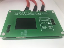
Electrodacus SBMS40 3D Brothers Edition Review Thread

I cant say I'm supersized. I installed a heat sink on the one I have and it still got to hot for my comfort. So I ran a PC fan at the heat sink. It still generated enough heat that the heat sink sagged notably( used thermo tape due to open circuit board). Between the massive error in Amps reporting and running to hot I gave up on the unit. On the plus side I was able to play with Dacian's software and now I have a SBMS0 DSSR20 with and without Diversion and a DEXT16 ( I plan on using Diversion to keep the FLA's floated between trips.
 
I cant say I'm supersized. I installed a heat sink on the one I have and it still got to hot for my comfort. So I ran a PC fan at the heat sink. It still generated enough heat that the heat sink sagged notably( used thermo tape due to open circuit board). Between the massive error in Amps reporting and running to hot I gave up on the unit. On the plus side I was able to play with Dacian's software and now I have a SBMS0 DSSR20 with and without Diversion and a DEXT16 ( I plan on using Diversion to keep the FLA's floated between trips.

I may end up doing the same thing. I was seriously considering buying an SBMS0 / DSSR20 combo yesterday, but given I have this device and it still works for system monitoring and control of external chargers, I will reconfigure my system to have an external SSR switched by EXTIO3 and use an MPPT charge controller I already have to charge the battery.

This is actually safer than charging via the PV circuit of the SBMS40 as the external MPPT charge controller will see the 4 cell battery voltage and can be programmed to stop charging at a conservative 13.8V for example, so the disconnect command which the SBSM40 will issue becomes the fallback in the event there’s any cell imbalance leading to one cell voltage being higher. With two devices monitoring the battery voltage to disconnect at top of charge, I have the redundancy @BiduleOhm referred to, even if only one of those devices is monitoring cell voltages.

The absence of balancing via the SBMS40 is a real drawback (arising from the fact Dacian’s software only enables balancing when charging current via PV circuit is above a 300mA threshold value). Maybe I can arrange some small charging device to put a nominal 0.5A current via that SBMS40 PV circuit with an EXTIO3 controlled SSR in line with it for disconnect at top of charge, just so I can maintain cell balancing. Or I’ll add an external balancer to the system.

With some care I reckon I can still make a functional system out of this, avoiding the €150+ cost of a new SBMS0.
 
Last edited:
Well this thread began three months ago as a review thread, and every review needs a conclusion.

There’s plenty I like about this device, Dacian’s Electrodacus software with its informative display and remote connectivity via wifi gives you a powerful tool for seeing not just what the system is doing right now, but also via the well implemented graphs, 12 hours of PV, battery and load current are there at a glance. I’ve enjoyed a better level of understanding of how my off grid system is working than I’ve ever had with the previous remote monitoring solutions from BMSs and charge controllers I’ve used before.

If I’m picky, I’ll say the size of the screen and tiny text doesn’t suit my middle-aged eyes, but this is solved by use of an iPad via wifi as remote monitor.

Beyond system monitoring, the expansion opportunities via the EXTIO connectors make this device more than a combined BMS and charge controller, but an overall system controller too, so adding more offboard charge controllers or switched loads becomes possible.

In using the device I’ve encountered some drawbacks, which I’ll summarise below:

- Lack of backlight control. Sounds like a small issue, but it becomes important when you wall mount the device and find the whole room lit up by it at night with the lights off. Anyone living in an RV with this device in the same living area will not appreciate the bright 24/7 illumination from the screen. Although Dacian’s software incorporates a timeout which should dim the screen, an incompatibility between software and the display used in this version means the backlight remains full-on full time.
- No provision for mounting. There are no screw holes or oversized ears, so just putting this on a flat surface in a secure way is difficult. The supplier Alex from 3D Brothers tells me they intend to offer a heatsink for the unit, which will incorporate mounting holes.
- Accurate calibration of the PV current was not possible with the supplied software. Alex has since adjusted the software to increase the PV shunt resistance range, which should eliminate this drawback and I believe the devices he ships to his indiegogo backers will have this software by default, so that’s a positive development.

Beyond those issues which I characterise as drawbacks, there’s one elephant in the room which cannot be ignored. My device burned out yesterday and overcharged my battery to a dangerous level. This should never happen in any BMS design, and if the battery had been one of the more volatile Lithium chemistries which Dacian’s software supports, the results could have been a house fire.

I respect the fact Alex offered these devices to forum members for review without cost and that he and his team are running a business and understandably wish to see a return on the time and effort they’ve put into redesigning Dacian’s circuit with mass production in mind, however I cannot overlook this failure and it makes it impossible to conclude this review in a positive way. I can’t recommend this as a product to buy, sorry to say :cry:

As I intend to continue using this device as the heart of my system, I may continue to update this thread with observations once in a while, but as far as the review goes, that’s the bottom line!
 
Last edited:
Thanks to extraordinary generosity on the part of @grizzzman, I’m back in the SBMS40 game with a replacement, undamaged unit. ? (y)

I will be putting this to work in my system, but will not be trusting it with charging currents of more than 15A and will take precautions with a SSR to provide a dual redundant disconnect to prevent overcharging in the event the CFET somehow burns out. Batteries are too expensive to take chances with.

27850CBC-7D03-4522-A06C-3584EEC85CC3.jpeg
 
Last edited:
With wiring harnesses attached for the PV, Battery and Load connections, plus an improvised multiway lead for the individual cell voltages, I’m ready to install this. Only when I approached my power wall with the thing in my hand did I realise, I don’t know how I’m going to screw this to the wall! There are holes in the back PCB, but I’m not sure they’re intended for mounting, and the four corner holes are occupied with the plastic stand offs.

Probably I’ll have to remove the standoffs and go thru those holes with a long self tapping screw, straight into the wall behind and make use of some spacers to hold the two boards apart. If anyone has a better idea please shout! View attachment 30640
I got one of these through the crowdfunder campaign, however, there was no connector for the balance leads, nor any info on what connector it takes or the pin-out for the balance leads. So, I can't use it.
Since you have added all that, can you tell me what connector it requires and point me to where the pin-out is?
I would greatly appreciate the help.
 
I got one of these through the crowdfunder campaign, however, there was no connector for the balance le ads, nor any info on what connector it takes or the pin-out for the balance leads. So, I can't use it.
Since you have added all that, can you tell me what connector it requires and point me to where the pin-out is?
I would greatly appreciate the help.
Would amazon links work for you? cable and Connector. If you plug in the USB, all wiring and operation info is in the unit. Or download the PDF file for the unit at the Electrodacus site.
 
Last edited:
I got one of these through the crowdfunder campaign, however, there was no connector for the balance leads, nor any info on what connector it takes or the pin-out for the balance leads. So, I can't use it.
Since you have added all that, can you tell me what connector it requires and point me to where the pin-out is?
I would greatly appreciate the help.
As @grizzzman said, there is some info in the manual but as per the screenshots below, it’s not super clear as it assumes you’re using a 10 pin colour coded cable which Dacian supplied with his units, so only the connections to be made at the far end of the cable are documented.

Nevertheless, if you zoom in on the pinout diagram showing the 10 pin connector, you can work back to figure out which pin on the header connector corresponds to each colour.

I used RC servo leads (3 pin) pushed onto the pins of the connector to make my own makeshift cable, but far better to get the right ribbon cable and 10 pin plug using the links @grizzzman provided.

The most important advice I can give - read back over the past page or two of this thread and note that this is not a 40A charge controller and isn’t safe at even half that current. Mine burned out on me, so please find a way of heat sinking the FETs or limit your solar setup to 15A.

AAFAAEB1-BB38-4358-B2D2-D57B54951086.png3355EE87-3A84-4D1D-9F5D-7E24DEB97CE1.png
 
As @grizzzman said, there is some info in the manual but as per the screenshots below, it’s not super clear as it assumes you’re using a 10 pin colour coded cable which Dacian supplied with his units, so only the connections to be made at the far end of the cable are documented.

Nevertheless, if you zoom in on the pinout diagram showing the 10 pin connector, you can work back to figure out which pin on the header connector corresponds to each colour.

I used RC servo leads (3 pin) pushed onto the pins of the connector to make my own makeshift cable, but far better to get the right ribbon cable and 10 pin plug using the links @grizzzman provided.

The most important advice I can give - read back over the past page or two of this thread and note that this is not a 40A charge controller and isn’t safe at even half that current. Mine burned out on me, so please find a way of heat sinking the FETs or limit your solar setup to 15A.

View attachment 52021View attachment 52022
Thanks, no worries, I do not expect this to be getting more than 10 amps.
 
Doesn't ElectroDacus have schematics on his website? You should be able to use an ohm meter to "buzz out" connections.
 
Doesn't ElectroDacus have schematics on his website? You should be able to use an ohm meter to "buzz out" connections.
They may, although I haven't found one that gives the pin out for the connector. And, the one I got is the re-design, so it is not laid out the way the original is. I am sure the 10 pin connector is likely the same, but likely is not for sure.
 
If you look carefully you will see a locating notch on the SCC 10 pin socket. The schematic clearly shows pin numbers and actual location.
 
The screenshots I posted on Tuesday show the connector with location of which pin to connect each of the wires which go to the battery cells for various configs, and also as Grizzman said, it’s displayed onscreen on the device when you configure it for how many cells you’re using. I’m not sure what’s still unclear?
 
The screenshots I posted on Tuesday show the connector with location of which pin to connect each of the wires which go to the battery cells for various configs, and also as Grizzman said, it’s displayed onscreen on the device when you configure it for how many cells you’re using. I’m not sure what’s still unclear?
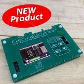
Well, the screen shot you posted from the manual is not for the electodacus that I have. I have the new re-designed electrodacus that looks like:
1623414016361.png

Then the picture shows the pinout based on wire color. Well, I did not get a connector or wires with my unit, so the colors are meaningless. Yeah, I can assume that the pinout is the same (just turned sideways), but I don't know that the pin out is the same--it was re-designed.
I did not get a connector, or wires, or a manual, or basically anything (not even a note) with my new re-designed Electrodacus--just a package with the BMS inside.
When they re-designed the BMS did they change any of the I/O? I don't know? There is nothing that I can find that goes through the re-designed BMS at all. Since I have never used this BMS before, I just wanted to make sure I hook it up correctly.
I got the connector and ribbon cable, now I just have to set it up and figure out how to use this thing.
 
It doesn't appear that the 3D brothers bothered to fix the silk screen issue on the EX port (At least the + is correct) But makes me wonder if there software issue was really addressed after the Demo units we got.
 
It doesn't appear that the 3D brothers bothered to fix the silk screen issue on the EX port (At least the + is correct) But makes me wonder if there software issue was really addressed after the Demo units we got.
In below video Alex shows the production batch units and the silk screen printing does align with the connector, so that did get fixed. The photo looks like it’s from Jehu’s webstore and will have been taken of a sample from the prototype batch.

Mind you, I’m also not confident that the software will have been properly fixed and tested and with no info being given to the users on calibration procedure, probably people will always struggle to get accurate readings. Dacian’s units were built right, so the SBMS40 manual never covered calibration.

 
> Lack of backlight control.

I can confirm that backlight is always on maximum on my SBMS40.

I've found another issue: After having an undervoltage condition, the flag is not reset after the batteries reaches the "Under Voltage Recovery" level.

My settings (LiPo batteries)

Under Voltage: 3.20 V
Under Voltage Delay: 1 s
Under Voltage Recovery: 3.60 V
Over Voltage Lock: 4.20 V
Under Voltage Lock: 2.98 V
Low Voltage Chg: 2.60 V

After charging the batteries the status was:
Cell voltages 3.8-3.9 V
Flags: CFET EOC UV

Holding down Menu/Load button turns off the UV flag and turns on the load again. But I don't want to go physically to the unit every time it happens :)
 
Well, the screen shot you posted from the manual is not for the electodacus that I have. I have the new re-designed electrodacus that looks like:
View attachment 52412

Then the picture shows the pinout based on wire color. Well, I did not get a connector or wires with my unit, so the colors are meaningless. Yeah, I can assume that the pinout is the same (just turned sideways), but I don't know that the pin out is the same--it was re-designed.
I did not get a connector, or wires, or a manual, or basically anything (not even a note) with my new re-designed Electrodacus--just a package with the BMS inside.
When they re-designed the BMS did they change any of the I/O? I don't know? There is nothing that I can find that goes through the re-designed BMS at all. Since I have never used this BMS before, I just wanted to make sure I hook it up correctly.
I got the connector and ribbon cable, now I just have to set it up and figure out how to use this thing.
I got this cable/connector and it fits just fine in the 10 pin connector slot. A little late, but...
 
Back
Top