diy solar

diy solar

Electronic Loads

HaldorEE

Solar Addict
Joined
Apr 20, 2020
Messages
1,633
I have been reading discussions about top balancing cells and I realized I need to be a bit more organized about this. So as part of that I think I will design a constant current, electronic load.

I am thinking about using one of the L2 family of Linear N channel MOSFETs from IXYS (Littlefuse).

This 100V, 110A MOSFET should be good to at least 50A without requiring esoteric heat sinks. Reason why I want to use one of the L2 series MOSFETs is they have are designed to be used in the linear region and have very generous SOA specs (less likely to let the smoke out).


Looking for suggestions about what would be a good C rate to use for capacity testing of LiFePO4 cells. I have a set of 280 AH cells that I am dying to test. 0.2C would be 56A which should be doable with this MOSFET.

What else would it make sense to add? I think I am going to focus on single cell application for now. There are plenty of multi-cell capacity testers on Amazon. I couldn't find anything with the kinds of discharge amp levels I am thinking of.

Here is what I am considering:
  • A discharge voltage cutoff circuit to disconnect the load when the battery reaches 0% SOC.
  • A constant current charge mode (so we can use an off the shelf 5V power supply).
  • A charge voltage cutoff circuit to disconnect the external power supply when the battery voltage reaches 100% SOC.
Since I have never designed a LiFePO4 cell charger/tester before I have some questions:
  • What is the appropriate voltage to stop discharging at? I see 2.5V commonly mentioned. Is this correct? Is this going to low? Not low enough?
  • What is the appropriate voltage to stop charging at? I see 3.65V commonly mentioned, but I have also see references to stopping at a lower voltage.
  • Do I need to add a soak timer or is it enough to just reach the specified max voltage then disconnect the charge source?
  • Are pots sufficient? I think for the first pass this is how I will do it. At some point it could make sense to add some smarts to make the process automatic, record charge/discharge time, calculate AH and internal impedance of a cell.
 
What’s the aim? You mention top balancing, but then also talking about discharge testing. Are you trying to build a rig to measure cell capacity? If so, your proposed CC charge with cut off when a cell voltage is reached will not be sufficient, as you’ll miss the last part of the charge, when a “real” lithium charger will taper the current while maintaining the termination voltage. The CV part of the CC/CV cycle.

But you’ve said you don’t need to CV charge, so maybe you’re not worried about getting 100% charge into the cell for a fair capacity test, so again, what are you looking to do?
I am looking to measure my cells capacity and then top balance them.

Capacity testing and charging to top balance will be done individually, after which I will hook them all up up in parallel and let them equalize together for a period of time: days, week, whatever it takes.

I think it will make a neat project. If I am happy with how it turns out, I will fabricate a PCB for it. A small prototype PCB is not expensive to have made. If there is interest I will have a small run of PCBs made and pass them on for cost.

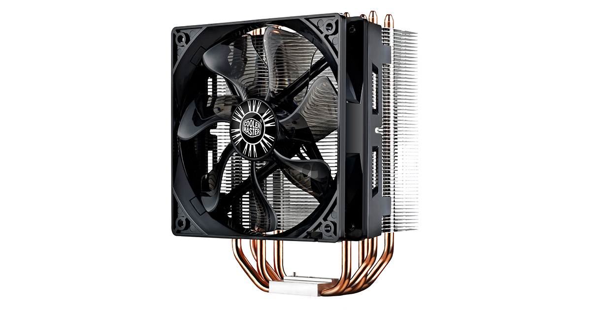
The limiting factor will really come down to heat sink capacity for the MOSFET. I was thinking about using a CPU cooler, but air cooled coolers top out about 250W. The Cooler Master 212 I used on my Ryzen 3600 CPU is rated for 120W of dissipation. If I use that one, I will limit max current to 35A.

 
your proposed CC charge with cut off when a cell voltage is reached will not be sufficient, as you’ll miss the last part of the charge, when a “real” lithium charger will taper the current while maintaining the termination voltage. The CV part of the CC/CV cycle.
That is related to my question about soak time. Everything I have read about top balancing says once you reach 3.65V you are at 100% SOC. No further charging is required. My further understanding is that it is dangerous to keep charging a cell once it reaches 3.65V. You want to reach that voltage, then disconnect the charger.

Here is what I think I am supposed to do:
  • Charge with CC until I reach a voltage of 3.65V.
  • Discharge with CC until I drop to a voltage of 2.5V.
  • Measure how long it took to reach the discharge voltage. This time multiplied by the CC rate will give me the cell AH rating.
Questions I am asking about capacity testing:
  • Are these the correct charge and discharge voltages for testing my cells?
  • What C rate should I use for the CC setting?
  • Is my understanding correct? Do I need to do anything besides this?
 
Last edited:
For top balancing, I will bring each cell to 100% SOC, then connect all the cells in parallel.

The cells I charged first will very likely have dropped back to 3.5V or thereabouts by the time I get the last cell charged up. Is is enough to just connect them all in parallel or should I connect the charger to the complete set of cells and bring the entire pack back up to 3.65V?

I am wary of overcharging the cells. I have heard enough horror stories from people who damaged their cells during top balancing to not assume I know what I am doing.
 
Dissipating 300W lineary on a FET isn't really a good idea.
You were ways better off PWM-transfering the power to a powerful resistive load...
Some 12W Car Immersion Heaters or Dashboard Windscreen Heaters in // could be that load.
 
That is related to my question about soak time. Everything I have read about top balancing says once you reach 3.65V you are at 100% SOC. No further charging is required. My further understanding is that it is dangerous to keep charging a cell once it reaches 3.65V. You want to reach that voltage, then disconnect the charger.

Top balancing and fully charging a cell are two different activities, and you may be correct that when top balancing, people do not emphasise that charging current should be tapered to get the cells fully charged - it’s because fully charging the cells is not the goal, balancing them is.

People may well refer to 3.65V as 100% SOC, but it ain’t necessarily so. For one thing, LiFePO4 cell voltage is known to suck as a measure of SOC and for another, your measured cell voltage will rise or fall depending on how much current you are putting into (or taking from) the cell. This is exactly the reason lithium cells need a CCCV charge cycle, because the first time your cells hit 3.65V with full charging current applied to them, their voltage is being supported by the charging current and would drop immediately if you halved or switched off entirely that current. Only if you taper the charging current with a CV phase at the end will you put the final couple of percent of charge into them.

You will fail to achieve your goal of an accurate capacity tester if your design uses only a CC phase, as you will not be fully charging the cells. What I’m telling you about CC/CV charging is not contentious, not simply my opinion, it’s the standard, well understood charge profile any accurate lithium cell charger uses.

The answer to your Q of what charging current is it does not matter, as long as it’s within spec for the cell. The higher the charging current you use, the more voltage is added to the “true” cell voltage, so the lower the true SOC will be on that first occasion you reach 3.65V, but that doesn’t matter, because your CV phase with tapering charge current will take up the slack.

If you want to persist with only CC charge and discharge then you have to accept you’ll be measuring less than the true capacity and the higher the charging current you use, the further you’ll be off the mark.
How about providing some information or links. I am not arguing, I said I never did this before and am asking for recommendations. Got a link to an appropriate charge profile?
 
This 100V, 110A MOSFET should be good to at least 50A without requiring esoteric heat sinks. Reason why I want to use one of the L2 series MOSFETs is they have are designed to be used in the linear region and have very generous SOA specs (less likely to let the smoke out).

Don't be surprised if these MOSFETs, even though documented for DC operation, aren't "Safe" to "Operate" in all "Areas" of its SOA.
There has been so much trouble with MOSFETs used for linear operation. NASA came up with a modification to the curves, cutting off steeper as voltage gets higher. But I don't know if there is a safe way to predict it.

I think the very low end of voltage e.g. one cell may be OK at full current. Not sure how high a battery voltage before you run into trouble. Since it is a thermal runaway issue, keeping the case very cool will help.

Maybe not esoteric heatsinking, but significant heatsinking none the less.

If you can size a fixed resistor placed in series with the transistor, able to take most of the power dissipation across the entire range of battery voltage, you'll greatly reduce stress on the transistor.

Dissipating 300W lineary on a FET isn't really a good idea.
You were ways better off PWM-transfering the power to a powerful resistive load...
Some 12W Car Immersion Heaters or Dashboard Windscreen Heaters in // could be that load.

PWM with an inductor and he'll have designed a switching current source.
I suppose with a capacitor and PWM into resistive load, could be reasonable. Maybe C1, R1, C2, MOSFET, R2.
Using switching of MOSFET into resistive load R2 to keep second C2 at a suitable voltage (with some ripple), current (C1 - C2)/R1 can be kept fairly steady.
 
Dissipating 300W lineary on a FET isn't really a good idea.
You were ways better off PWM-transfering the power to a powerful resistive load...
Some 12W Car Immersion Heaters or Dashboard Windscreen Heaters in // could be that load.
Read the data sheet for that MOSFET. Dissipating high power in the linear mode is precisely what that part was designed for.
 
Read the data sheet for that MOSFET. Dissipating high power in the linear mode is precisely what that part was designed for.

Designed for, but don't be surprised if the published SOA isn't entirely accurate.


You may be OK, but if not you'll end up with a melted blob of silicon, crater where it blew out of the molding compound, and if you're lucky the wire bonds make a nice fuse.
I suggest putting a suitably rated fuse in series.
 
What is an appropriate charge/discharge profile to use for testing single cells? I can certainly do CC followed by CV if this is a requirement. If a soak stage is required, then how long is appropriate? Since this is a single cell I don't need to hold near full while cell balancing is taking place.

I am going to be using these cells in a solar power application so high C rates for prolonged periods of time are not of interest to me. Does it matter which C rate I use for my testing? LiFePO4 cells are not supposed to suffer from Peukert effects to any significant degree and its not like I am going to be cycling the cells more than once or twice. For my cells, 0.05C = 14A, 0.1C = 28A, 0.2C = 56A. Obviously higher C rates will let the testing completes faster, but I also don't want to make this tester more expensive than necessary.

I have no idea how anything other than a CC discharge profile is appropriate, am I supposed to tail off the discharge current as I reach the low voltage cutoff? I have never heard of a load that does that. Nothing I power from these cells is going to behave in that manner.

These parts ARE used in electronic loads in precisely the way I intend to use them. This is what the manufacturer designed them to do (read the attached document. I have seen 100A electronic loads designed with 3 of these in parallel (actually the 90A version). I expect that one 110A part should have no problem handling 35A.

Would anybody consider answering any of the the questions I have asked?
 

Attachments

  • LinearL2TM.pdf
    974.8 KB · Views: 4
Read the data sheet for that MOSFET. Dissipating high power in the linear mode is precisely what that part was designed for.
Physics laws apply to high power MosFETa as well.
To dissipate 500W you need a huge heat-sink. Period.
The data sheet always assume an infinite heat-sink.
But you are free to try else and build your experience yourself.
 
Designed for, but don't be surprised if the published SOA isn't entirely accurate.


You may be OK, but if not you'll end up with a melted blob of silicon, crater where it blew out of the molding compound, and if you're lucky the wire bonds make a nice fuse.
I suggest putting a suitably rated fuse in series.
I understand your concerns. Those IRFP FETs have a negative temperature coefficient which means when they overheat, they go into thermal runaway. Linear Trench FETS have a positive temperature coefficient (resistance increases with temperature) so they are not subject to thermal runaway. Like I said, these parts are designed to be operated in the linear region without burning up.

The minimum SOA for this particular part is 575W, I propose limiting my usage to a max of 120W (to fit within what a reasonably priced CPU heat sink can handle). That still permits me to sink 35A continuously (DC, not pulse).
 
I would encourage you to look at some other DE Electronic Load designs. As it has been mentioned - operating in the linear region of a MOSFET is a challenging task where you are likely right on the edge of disaster at any given moment.

Commercial designs use various switching topologies and I believe there are a number of DIY projects out there.

Many years ago, I went the eBay route and purchased some HP/Agilent and some Chroma units cheap. At this very moment, I am using them to do exactly what you describe - qualifying LiFePO4 batteries. The nice benefit to getting an old lab grade instrument is that I am able to fully automate them using Python and GPIB. I get very precise and detailed results.

If you just want the learning experience of DIY - all good. Perhaps take a look at the projects found on eevblog.com forum.
Great place to learn about this kind of thing.
 
I am looking to measure my cells capacity and then top balance them.

The limiting factor will really come down to heat sink capacity for the MOSFET. I was thinking about using a CPU cooler, but air cooled coolers top out about 250W. The Cooler Master 212 I used on my Ryzen 3600 CPU is rated for 120W of dissipation. If I use that one, I will limit max current to 35A.

A simple heat sink that is very effective for big diodes or Mosfets is to remove the aluminum head from a junk lawnmower or other small 1 cylinder engine and fasten the semi conductor to it. Big fins, lots of metal, and free.
 
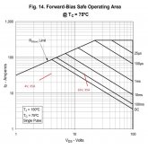
Looks to me like that transistor should be safe for one cell, 4V at 35A. But not a 12V battery, 16V at 35A.

X SOA.jpg
 
Speaking of diodes - another way to shift some/most power dissipation out of the transistor.
Series connection of heatsinked diodes would serve as as non-linear resistor. Jumper to the voltage drop you want depending on what you're testing.
Forced air will provide much more cooling than convection.
 
Back
Top