diy solar

diy solar

Electronics questions

Solarfun4jim

Solar seduced :-)
Joined
Sep 22, 2019
Messages
743
Location
Sunny Scotland
Totally different world to me...so just picking up info at present....

1/ If looking to use mosfets to switch loads up to 64V64A (>4Kw) , would good practice dictate using a single power mosfet with large heatsink or paralleling several fets to achieve the parameters needed?

2/ Any recommendations on a control chip that can control 144 mosfets, each 1/10th sec, using data input reference of 16 cells? Along with this, are there any recommended websites that would produce programming code if you set the parameters?

Just exploring possibilities. :unsure:
 
1. 64 A is do-able no problem with one mosfet but if you want no heatsink you'll need a pretty good mosfet (Rdson < 1 mOhm) so usually it's cheaper (and you'll have less losses) if you parallel multiple mosfets. In your case 3 or 4 mosfets should do the trick.

2. 144 mosfets? that's a lot... They are controlled by the same signal (i.e. all ON at the same time and all OFF at the same time) or they must be independent from each other?

100 ms, okay, but that's what parameter? the ON duration? toggling on/off each 100 ms? ...

I don't understand "using data input reference of 16 cells?", please give more details.

Along with this, are there any recommended websites that would produce programming code if you set the parameters?

Probably not. Depends on how simple your project is so I need more details to be able to answer.
 
Last edited:
Thanks for the reply biduleohm....i know you are busy with your project with Cass.
Bear with me....only idea's and probably not workable....
For charging purposes...
I'm looking to take the 'BMS monitoring voltages' from a 16S battery and use that to open 16 out of 144 switches(fets). I just plucked a time figure out the air, to open and close these switches. In the first 1/10th of a second, the lowest reported cell gets a 64A switch opened, 2nd lowest cell, gets 32A, third gets 16A etc down to cell 8 gets 0.5A and cells 9-16 get 0.0625A. (If total available current is lower, it would still be allocated proportionally). Thus every cell gets some current, but the lowest cell gets the most current for that time period. (I'm assuming with DC then the time period doesn't have a great impact, unlike AC requiring 50hz etc?) The cycle then repeats for the next 1/10th of a second. In this way, the main amperage is directed at the lowest cell all the time, thus keeping them balanced throughout the whole charge process, irregardless of the charging voltage set or how small of a charge there is taking place in the cycle. ie in most current methods a lot of balancing appears to be done mainly in the 'legs' at a fairly extreme voltage( eg little balancing done if charging at 3.4v/cell).
Regards the mosfets, they are all zero powered 'off' till the signal is given by the controller, then 16 fets open at the same time(individually controlled).
I dont know anything about control chips whatsoever, but i presumed 16 data inputs could be converted to 16 'on switches' signals, depending on their respective levels. The remaining 128 fets would be zero voltage until activated.
I'm probably rambling twaddle...but any info you give is very well recieved.
Thanks.
 
I have a déjà-vu feeling... that's more or less what you described on the BMS thread :)

I have a few questions:

How do you limit the current to 64, 32, 16, ... A?

Can you do a schematic (with simple regular switches instead of mosfets and only 3 or 4 cells (12 V pack for example) and only 3 levels of current instead of 16)? I've a very hard time to understand how it would work.

BTW to do what you want to do we're looking at about 1 to 2 dollar of mosfet per switch, if you want 144 switches (and I bet you'll need at least double that...) that's 144 dollars best case just for mosfets... 16 levels are super uber overkill, 3 or 4 would be plenty enough IMHO and would reduce the cost (and size) a lot.
Old school for splitting the amperage proportionally, electronics for controlling the fets.
Where you are looking at a BMS type system, it would be very difficult to control costs on such a small unit. A 'all in one' charge controller/BMS combo, where you could 'plug n play' by adding PV, alternator, gen set, grid/shore powerAC all regulated with their individual modules, gives a lot more scope to increase cost components in some area's and reduce in others.
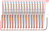
I think the diagram below should effectively 'old school' direct the current proportionally 'hard wired', no need for electronics to do that, especially when handling up to 64A
The grey boxes are the fets which need opened to the busbars below. Each rail only supplies one cell except for the 0.5A split at the bottom, which supplies the 0.0625A to the remaining 8 cells. Thus every cell is constantly being charged, just to varying degrees.

1 second current allocation layout example.png
 
Last edited:
The text is barely readable (that's the forum fault; it downsize the images and it doesn't put a link to see the original hi-res image...) but if the grey boxes are the mosfets then I don't see anything to limit the current.

For example what happens when the top right mosfet closes? because personally I see 48 V fed to one 3 V cell (cell 16) and the laws of physics will resolve this problem quickly and with a lot of smoke... ?
 
All mosfets are closed. Only 16 mosfets are opened on signal.
Incoming amps =128A. This splits into two, giving a top rail of 64A. The second leg 64A, splits into two giving two 32A legs.... and so on.
The signal from the lowest cell, will activate one cell on the top rail, which feeds one cell. The next lowest cell, would activate the signal to the 32A rail and so on.

For example cell 2 is lowest. The top rail is 64A, mosfet 2 on top rail opens...no others on the top rail.
Cell 5 is next lowest....mosfet 5 opens on the 32A rail. Cell 16 is next lowest, so mosfet 16 on the 16A rail opens....and so on.
 
Last edited:
If all mosfets are closed then all the cells are shorted...

Actually if any more than one mosfet is closed then you have a short (unless if they are on the same column).
 
If all mosfets are closed then all the cells are shorted...

Actually if any more than one mosfet is closed then you have a short (unless if they are on the same column).
If all mosfets are closed, how can any power get to the cells...there is no path. On each 1/10 of a second, 16 mosfets are open allowing current to pass, ie 1 opens on each rail.
 
I'm not explaining myself very good...

Another example...

Cell 1 is lowest, mosfet 1 on the top rail opens and supplies current to the line one busbar. This is the only current going to cell1
Cell 4 is the next lowest, mosfet 4 on the 32A rail opens. This is the only current being supplied to busbar line 4(cell 4)

Hope i'm making some sort of sense??

At any given time, there will only be on live current carrying cable to each busbar.

ps closed mosfet i'm assuming means 0V no current passing, open means they are seeing 5V? (just in case my understanding is wrong)
 
Last edited:
Ok, there's a big misunderstanding: mosfet closed = switch closed = current passes, mosfet open = switch open = current can't pass.

Cell 1 is lowest, mosfet 1 on the top rail opens and supplies current to the line one busbar. This is the only current going to cell1
Cell 4 is the next lowest, mosfet 4 on the 32A rail opens. This is the only current being supplied to busbar line 4(cell 4)

Hope i'm making some sort of sense??

Yes, that makes sense.

Now the question is: what's limiting the current on each rail?
 
Parallel circuits. 128A input splits into 2x 64A. one leg of the 64A splits into 2 x 32A, one leg of the 32A splits into 2 x 16A
Effectively, you have this....

parallel circuits.png
 
Last edited:
If you use resistors you can do that but only for a passive load. Here you need to account for the fact cells have voltage.

Also if you have nothing to limit the current you'll get everything the source can provide as soon as the switch you close isn't on the first column because you'll have a big voltage mismatch (as much as 48 to 3 V for the cell 16).

The only way to do what you want to do is either to have current sources instead of voltages source, one for each rail, or either to use isolated DC/DC converter (but we're talking hundreds if not more than a thousand dollars for the currents at play here).
 
Ah right, will need to give my lonely brain cell time to digest that.....lol.
Appreciate your help. (y)
And if you regulate the voltage to match each cell, that knackers up your Amps....oh well
 
They use inductors or capacitors (usually super capacitors) to store energy from one cell and give it to another cell.

They use switches on both pos and neg so they can take energy from any cell and then connect to another cell to give the energy back. Imagine using a bottle to transfer water from a bucket to another one, you don't really care about height difference between the buckets because your bottle is isolated from one when your doing something with the other.

They are like isolated DC/DC converters function wise but they can only work 50 % of the time, unless you use two storage devices and 4 switches, by taking energy with one while the other gives back its stored energy to the other cell, and then doing the opposite, you can have a nearly continuous energy transfer.

With super caps the efficiency can be really high (I'm sure you can be at 98-99 % no problem with good design and components).
 
Last edited:
I use 110A FET for only 10A loads. Maybe that's just me. No time now.

No that's usual, a 110 A mosfet can only pass 110 A with very very good cooling (like water cooling for example) so it's a well known thing to over spec the mosfets. Also, higher current mosfets often have a lower Rdson so less losses.
 
Back
Top