diy solar

diy solar

Elejoy EL-MD, WARNING ⚠️, high voltage Backfeed!

Vi s

Learning
Joined
Dec 6, 2020
Messages
340
Location
Thailand
New post:

Warning: This cheap charge controller feeds back over 90V to solar input after charge stop. This high volt feedback voltage destroyed one of my bench power supplies. I guess after charge stop the capacitors inside discharge!? Neither the battery (used a 12 volt one) nor my now destroyed power supply (up to 24volts only) was able to produce 90+volts so it definitely comes from the charge controller.
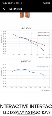
Also the efficiency of it was not as advertised. Further the readings of those meters are off quite a bit. Better stay away from this controller.


Old post:
Hi

I just found these super efficient (97 to 98%!! in real life as seen in three different YouTube videos) but still affordable (200W to 400W for just around 30usd) charge controllers, the Elejoy EL-MD series.

Wanted to ask if anyone has one of those elejoy charge controllers? What is your experience?

How high is their self consumption? Can you second the incredible efficiency of up to 98%!?
 
Last edited:
Link?

Betcha they're fraudulently listed PWM controllers.

PWM controllers tend to be very efficient because they are simply shorting the panels to the battery. They're not doing anything meaningful until absorption voltage is reached, and they begin rapidly connecting/disconnecting the panels hundreds/thousands of times a second to maintain the voltage and limit current.
No no not fraudulent at all.

~29usd at aliexpress


Watch this to check whether pwm or mppt

 
Last edited:
Features:
With the LED display to show the input and output current and voltage, you can see the data more clearly. The output voltage can be adjust between 10~30V, you can choose the suitable for your needs.

Suitabe for the le-ad-acid, lithium-ion and other batteries in line with 10~30V recharging voltage.

Efficient MPPT real-time tracking function, give you a better using experience.

Overheat pro-tection function: When the internal ambient temperature of the MPPT controller exceeds 100℃, the output power of the MPPT controller will be reduced. If the internal ambient temperature continues to rise to 110℃, the output of the MPPT controller will be automatically turned off. When the internal ambient temperature of the MPPT controller falls below 85℃, the MPPT controller will automatically resume operation.

Short circuit pro-tection function: when the MPPT controller output comes unexpected short circuit, MPPT controller will automatically close the output, the short circuit will automatically return to normal after elimination.

Input under-voltage pro-tection: when the MPPT controller input direct current voltage is lower than 15V, MPPT will protective shutdown, the input voltage is normal automatically resume work.

Specifications:
Material: aluminum
Suitable for: the battery of recharging voltage between 10~30V
Suitable solar panel: The open circuit voltage: 18V~55V
Maximum power voltage: 17V~55V
Output power: 200W, 300W, 400W (optional) Photovoltaic input starting voltage: 18V~55V
Photovoltaic input tracking voltage: 17V~55V
Output to the battery voltage: 10~30V (adjustable)
Output to the battery current: Max.25A
No-load loss: 0.35w
The pi-tch of the installation: 110mm * 70mm Installation hole diameter: 5mm
Voltage adjustment rate: 1%
Load adjustment rate: 1%
PWM conversion efficiency: 97%
MPPT efficiency: 99%
Working temperature: -40℃~65℃ Install line length: 50mm Item size: 130 * 80 * 40mm / 5.1 * 3.1 * 1.6in Item weight: 450g / 1.0lb Package size: 160 * 90 * 50mm / 6.3 * 3.5 * 2.0in Package weight: 500g / 1.1lb
 
Yep. Constant voltage output. Useful for that need, but poor choice for battery charging unless you're cool with float charging only. This would be good for 3.6-3.7V Li-ion chemistries, but not so much for LFP.

Very poor choice for lead-acid as it has no ability to apply temperature compensation.
 
Yep. Constant voltage output. Useful for that need, but poor choice for battery charging unless you're cool with float charging only. This would be good for 3.6-3.7V Li-ion chemistries, but not so much for LFP.

Very poor choice for lead-acid as it has no ability to apply temperature compensation.
Why do you think not good for lfp??
Output voltage can be adjusted so it cuts at designated voltage as usual or!?

Yes for lead acid maybe not the best.
I use lifepo4 so I think it should fit me.
 
Lead acid and LFP need very similar charge profiles.

Unlikely the unit just cuts off. It likely tapers the current to hold that voltage. The only safe voltage for that behavior is 3.4V/cell or 13.6V for a 12V LFP. It will take you a LONG time to charge at that voltage level, and you will only get to about 95% SoC.

I would spend 2X the price of that unit for a proper MPPT. It's a novelty with a niche application and could possibly do damage if you don't know what you're doing with it.
 
Why not good for lfp?? It cuts at designated voltage or?

Yes for lead acid maybe not the best. I use lifepo4

Lead acid and LFP need very similar charge profiles.

Unlikely the unit just cuts off. It likely tapers the current to hold that voltage. The only safe voltage for that behavior is 3.4V/cell or 13.6V for a 12V LFP. It will take you a LONG time to charge at that voltage level, and you will only get to about 95% SoC.

I would spend 2X the price of that unit for a proper MPPT. It's a novelty with a niche application and could possibly do damage if you don't know what you're doing with it.
LFP and La need similar charging profile? You mean cc cv?

No issue since I intend to stay in the manufacturer (in this case EVE) recommended window of 10% to 90% for my cells.

For my setup for example, 4s 50ah lfp, 50w panel, 3.5A at 13.6v (3.4v) and 3.5a at 14v (3.5v = 99%) that's a difference of just 3W =6%. So yes it takes longer but not that much.

2020102459691545.jpg
 
Last edited:
Lead acid and LFP need very similar charge profiles.

Unlikely the unit just cuts off. It likely tapers the current to hold that voltage. The only safe voltage for that behavior is 3.4V/cell or 13.6V for a 12V LFP. It will take you a LONG time to charge at that voltage level, and you will only get to about 95% SoC.

I would spend 2X the price of that unit for a proper MPPT. It's a novelty with a niche application and could possibly do damage if you don't know what you're doing with it.
I have a jbd smart bms to protect the cells against damage. But in general, whatever you are doing or using, even with a 10x more expensive controller, if you don't know what you are doing you will likely cause damage. That's a given in diy that you should know what you are doing if you don't want to cause damage. And even if you know, mistakes happen. ??
 
How do you plan to stay between 10 and 90% SoC? Most folks have no idea how challenging this is.
 
How do you plan to stay between 10 and 90% SoC? Most folks have no idea how challenging this is.
Yes I do. Not too much if you know the charge and discharge curve of your cells and can able to set the charge and discharge voltage point. Or is there anything else needed? I mean I do not care about +-2% or so.
 
Yes I do. Not too much if you know the charge and discharge curve of your cells and can able to set the charge and discharge voltage point. Or is there anything else needed? I mean I do not care about +-2% or so.

If it were that easy, everyone would be doing it. What's the 90% SoC voltage for you?
 
47.7ah is 90% capacity of my 53ah lf50k cells.
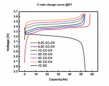
So according to the charge curve above at 0.2c it is about 3.36v per cell.
For me i have to make my own charging curve with a battery analyser and charge with 0.07c (3.5A) or simply discharge my battery and charge 47.7ah (see in bms) and check the voltage.
 
Discharge battery (12.8v 53ah) and charge 610wh (90% capacity) and read voltage. Then set charging parameters in charger and bms accordingly.
 
That will fail:
  1. 0.2C is 10A. if you charge at less than 10A (3.5A), you will be at a HIGHER state of charge at 3.36V/cell than you would be at 10A.
  2. The charge parameters you set will not terminate charging. The charger will continue to feed current at the set voltage level until the battery will take no more. This will almost certainly result in a near 100% SoC.
  3. The flatness of the voltage curve and the low charge current will make accurately targeting 90% very difficult.
  4. Using the BMS to cut the battery out of the circuit is NOT a good idea. You want the equipment working within the desired range and the BMS out of sight waiting to protect the cells if something goes awry.
You will have to MANUALLY terminate charging, or you will overshoot your 90%.

Is this a DIY battery? If so, have you top balanced your cells?
 
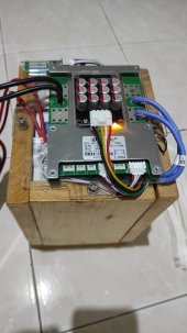
IMG_20210625_152708.jpg

Yes a DIY.
Yes I just top balanced at 3.627/8v and 0.2a (I stopped there) a few days ago. My pack has 0 cycles yet.

That was only an example of methodology but I also wrote I have to make my own charging curve with 0.07c/ find out where the ~90% in my scenario is.

I will use following method. Charge with my imax b6 mini full to about 3.63v/0.2a per cell. That is about 99% or 100% of rated capacity. Then I discharge 15% off the pack and charge again 5% with 3.5a and read the voltage. So I will set my cut/overvoltage protection (not float or whatever) at that voltage and the release at something less.
 
My diy battery and system is not yet 100% finished, waiting for missing parts. I will attach a busbar, breakers, an inverter and the charge controller to the wooden battery compression housing. Will become something like a power box (all in one package) where you just need to attach the solar wires.
 
Which 2x times more expensive charge controller would you recommend and why? Epever 1210an?
 
Back
Top