diy solar

diy solar

Elementary fuse block questions

LetMeHarnessTheSun

New Member
Joined
Apr 2, 2022
Messages
5
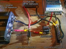
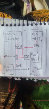
Hey all, I'm building my first Solar setup and want to make sure I do it right. I'm setting up a system based on Will's 400W design. I'm looking at 360W solar panel, 2000W inverter, 206ah 12v lithium battery, and 40a MPPT. My question was regarding fuse, fuse block, and circuit breaker sizing.

So if I understand correctly,
2000/12= 166~ X 1.25 = 208~
So I would require a 250 amp circuit breaker on my main connection.

When I went and looked at the fuse box for DC appliances I notice it reads "Suitable main circuit connection of not more than 125A rating should be provided ahead of this device..." And the diagram shows a 125A fuse before the fuse block.

This is where my rudimentary knowledge of electricity comes in.

Am I going to fry my fuse block if there's no 125A fuse there, is it only dependant on the amount of power I intend to draw from the block (Will be used to charge phones, vent fan, lights, etc. Nowhere near 125A), or do I install a 125A fuse behind my 250A circuit breaker?

Sorry for what's likely a painfully basic question, I've gone mental figuring this all out, anything helps at this point.
 
So I’m going to make some assumptions based on having dug around in more than a few campers in the past and ‘conventions’ one would (should?) expect for a 12V system.

It sounds like the 12V fuse box is rated for 100A having a slightly overrated fuse at 125A. This would leak me to assume the battery to fuse box wire is 4AWG- I would verify that. (Personally I would use a 100A fuse for a 100A fuse box)
Am I going to fry my fuse block if there's no 125A fuse there
so the factory did not install this 125A fuse or breaker close to the battery? Maybe a pic of this oem fuse box is in order.

The fuse box has to have a fuse between it and battery as close to battery as possible. The fuse rating should be ‘technically’ not more than 15% or some say 25% above the rating of the wire that it protects. In this case should be 4ga or 2ga; 4ga at a minimum.
That’s problem one solved.
So I would require a 250 amp circuit breaker on my main connection.
or do I install a 125A fuse behind my 250A circuit breaker?
You could feed the fuse block with its 125A fuse ‘behind’ the 250A fuse. Or breaker.

A better way is to feed the fuse block and the inverter with separate cables both connected to the battery behind a fuse or breaker. Better still might be to run protected cables from battery inside to pos(+) and neg(-) busbars, and then feed the fuse box from those with the fuse at busbars and perhaps the inverter with or without a fuse/breaker if at-battery fuse is in place. I’d probably fuse inverter ‘again’ with the 250A at the busbar. 2/0 cables at 105*C should be ok between batt and busbars.

Because I would not supply inverter from that oem fuse box.
Am I going to fry my fuse block if there's no 125A fuse there
That is possible.
Assuming that the fuse box rating is correct is appropriate. 100A rating would seem usual.
~~~~~~~~~~~~~~~~
Do you ‘need’ a 2000W inverter? Coffeemakers could be 600W-900W, a vacuum cleaner 500W-1200W. (My 6-gal shopvac is ~800W} A microwave could be 1600W down to 900W. And a 1200W inverter will be ~100A at nominal 12V. I lived 3+ years on a 1200W giandel including almost a year running an electric fridge 24x7. No microwave or hair dryer.

I’d assess your needs and see if you need a 2000W inverter or not. I’d also future-think and at least plan for 800W of panels unless you are sure you’ll never want more charging capacity. I’d also evaluate if one of these makes sense for you.
 
A correctly engineered system will differ somewhat from demonstration arrangement produced to illustrated a design.

Fuses or breakers should be used at the power source, the battery, to protect the cable and what is on the end of the cable.
If there are multiple connections to the power source then each connection should be fused/ breaker as necessary.

My approach is to have a 'master' fuse directly on the battery bank positive post, with a suitable cable feeding a fuse array fitted with midi fuses, 30 to100 amps, and mega fuses 100 to 500 amps. Use a positive buss bar with fuse holders or a fuse distribution unit that combines the buss bar and fuse holder.
This fuse array (or breaker array) feeds via suitable cable each part of the system. In this case a feed each for the inverter, MPPT, fuse box.
My personal preference is to use fuses rather than breakers, many low cost breakers are unreliable .
Will add a diagram later.
diy 22a.jpg
Mike
 
Last edited:
Could you confirm what battery you are using?
If the 206Ah battery is a SOK the maximum continuous current is 100 amps.
This has a significant effect on the system.

Mike
 
the maximum continuous current is 100 amps
Very good point I totally didn’t think of.
(I have lead acid which ‘in any number’ will (to a point) just give out whatever you load them with until they die)
It would need at least two to support a 2000W inverter at full load.
 
Fuse protect wires. Size the fuse to the gauge of the wire to the fuse block. Select the wire gauge using a voltage drop table. Then select the fuse ampacity to protect that wire. What I have; 100 ampere Blue Sea fuse block. 2 awg marine cable, positive and negative, from BusBars to the fuse block. 200 ampere fuse at BusBar.
My 2000W inverter, 2/0 cable three feet from battery. 250 ampere fuse at positive BusBar. 300A fuse at each parallel battery positive.
You will find you need at least two of those batteries. Or no 2000W inverter.
 
So just to clarify, the system in this picture doesn't make sense, or it's just for display and not a usable system? He's got the battery running to a 200A fuse which runs directly to the fuse block.

Why shouldn't I get a 2000W inverter? In the inverter video it was suggested to upsize everything as much as possible. Will even suggests buying a 6000w inverter if you can afford it (which I can't). It's more than I need currently but I'm not trying to have to buy a brand new system next year.

Yeah I had the Sok battery in mind. Are there better alternatives? How does the continuous current affect the system.

I don't even have the parts of the system yet. I'm trying to figure out what I need. It's all projected.
 

Attachments

  • website-design-solar-system.jpg
    website-design-solar-system.jpg
    167 KB · Views: 30

A correctly engineered system will differ somewhat from demonstration arrangement produced to illustrated a design.

Fuses or breakers should be used at the power source, the battery, to protect the cable and what is on the end of the cable.
If there are multiple connections to the power source then each connection should be fused/ breaker as necessary.

My approach is to have a 'master' fuse directly on the battery bank positive post, with a suitable cable feeding a fuse array fitted with midi fuses, 30 to100 amps, and mega fuses 100 to 500 amps. Use a positive buss bar with fuse holders or a fuse distribution unit that combines the buss bar and fuse holder.
This fuse array (or breaker array) feeds via suitable cable each part of the system. In this case a feed each for the inverter, MPPT, fuse box.
My personal preference is to use fuses rather than breakers, many low cost breakers are unreliable .
Will add a diagram later.
View attachment 89606
Mike
Thanks a ton, this diagram really helps. In regards to breakers vs fuses, my worry is that with fuses being sacrificial if something does blow (I'll be living in remote locations for 3+ months with no access to shopping) I'll be left without power until I can get back into town. Are there brands of breakers that are more reliable, or things to look out for when shopping? Or is it safe to assume with everything hooked up correctly and without high power draw that the fuse won't blow?

I've drawn up a diagram of what my system would look like, let me know if everything looks right. The arrangement is pretty poor, moreso just a diagram to make sure things are connected properly.

Thanks again for the help you guys, it means a lot.
 

Attachments

  • 20220402_155713.jpg
    20220402_155713.jpg
    97.7 KB · Views: 29
A 2000 watt inverter at rated power will pull almost 200 amps from the battery. The 206 Ah SOK battery is limited to 100 amps continuous output. Thus the biggest inverter you can safely use with the SOK is 1000 watts.
Decide what actual ac power you need, select the the inverter for that power.
Then select the a battery or two batteries in parallel, that can deliver the current.
The 206 Ah SOK can deliver 100 amps x typical voltage 12.8 = 1280 watts continously

The system in the picture works electrically but is not best engineering practice. It would possibly fail a safety inspection if the system were installed in an application that needed certification. As you point out the fuse block is only rated for 100 amps, so any feed cable needs a fuse at 100 amps or less.

Mike
 
The fuses look sized correctly and should never actually disconnect unless there is something extraordinary that needs fixed.
Or carry some spares but I doubt they get used.
 
Reliable breakers from Blue sea or Bussman. Expect to pay upwards of $60 each.

Rough diagram looks fine , the breakers or fuse need to be as near as possible to the buss bar apart from the main battery fuse that should be near to the battery.

You still need to review the SOC 206 Ah battery as it limits the current in the system. You could use two 100Ah SOK wired in parallel as an alternative.

When it comes to wiring up the system you need to select the cable for the expected current.


Mike
 
A 2000 watt inverter at rated power will pull almost 200 amps from the battery. The 206 Ah SOK battery is limited to 100 amps continuous output. Thus the biggest inverter you can safely use with the SOK is 1000 watts.
Decide what actual ac power you need, select the the inverter for that power.
Then select the a battery or two batteries in parallel, that can deliver the current.
The 206 Ah SOK can deliver 100 amps x typical voltage 12.8 = 1280 watts continously

The system in the picture works electrically but is not best engineering practice. It would possibly fail a safety inspection if the system were installed in an application that needed certification. As you point out the fuse block is only rated for 100 amps, so any feed cable needs a fuse at 100 amps or less.

Mike
Thanks again Mike.

So it seems the Sok might not be the battery for me. Suppose I opted for something like the renogy 200ah battery that is rated for 200a continuous, would this solve the problem? Or would it be better to have a second battery wired parallel? How does wiring batteries together affect the continuous output? I.e if I had 2 Sok batteries, would that give me 200a continuous or remain 100a with greater capacity?

I'm trying to leave myself A LOT of overhead, as this vehicle may be my permanent residence as I build my property. It's currently only required for very small loads, but in the event I end up having to run a fridge/cooler, induction plate, computer, etc. in the future I don't want to have to start from scratch. As an induction plate runs at 1200W, a 1000W inverter won't suffice for me if I understand that correctly.

Be honest with me, how unreasonable am I being by oversizing this system? Will the components suffer if I'm not using them to max potential? I plan to leave room for more batteries/panels in the future.
 
If the majority of the loads are going to be AC loads and the inverter needs to deliver up to 2000 watts then you may wish to consider a 24 volt system. This reduces the expected currents by half and a less expensive solar controller can be used. ( the controller cost increases with current output)
An additional unit, a 24v to 12v DC to DC converter would be needed for small 12v DC loads.

The power in the system remains the same with twice the volts and half the current.

Since the limiting factor with most off the shelf batteries is continuous output current ( limited by the internal BMS) you will have more options of battery type and inverter power.

However the energy has to come from somewhere and if the only energy source is solar the panel array, size will be the limiting factor. Location, shading and sun hours will need to be considered.

Your questions on batteries, for a 12v system, two 12v batteries in parallel double the available power and also double the continuous current.
As for oversizing that should not be a problem based on you future expansion. You loose a little on efficiency by running a powerful inverter at light loading but that's not the end of the world.

Will your property be on the grid when completed?

Mike
 
Last edited:
So it seems the Sok might not be the battery for me.
Since you need 200A of continuous discharge current you can use two batteries in parallel. You can use 2 of the 12V 100Ah SOK batteries (total of 200Ah) or 2 of the 206Ah SOK batteries (total of 412Ah). Either would give you a total of 200A continuous discharge current.
 
If the majority of the loads are going to be AC loads and the inverter needs to deliver up to 2000 watts then you may wish to consider a 24 volt system. This reduces the expected currents by half and a less expensive solar controller can be used. ( the controller cost increases with current output)
An additional unit, a 24v to 12v DC to DC converter would be needed for small 12v DC loads.

The power in the system remains the same with twice the volts and half the current.

Since the limiting factor with most off the shelf batteries is continuous output current ( limited by the internal BMS) you will have more options of battery type and inverter power.

However the energy has to come from somewhere and if the only energy source is solar the panel array, size will be the limiting factor. Location, shading and sun hours will need to be considered.

Your questions on batteries, for a 12v system, two 12v batteries in parallel double the available power and also double the continuous current.
As for oversizing that should not be a problem based on you future expansion. You loose a little on efficiency by running a powerful inverter at light loading but that's not the end of the world.

Will your property be on the grid when completed?

Mike
As it stands, the majority of what I'll be running off of it will be 12vDC. Vent fan, phone chargers, interior lights, etc. The larger AC appliances will likely be used down the line.

I looked into adding a DC-DC converter to get power from my vehicle alternator as well, but was unable to find something suitable, got confused and gave up. Renogy has a DC-DC charge controller but it didn't meet the voltage requirements of my panel. (Panel Voc = 46.6 and controller reads max input voltage of 25V)

The property will likely be off grid as well, however this is 3-5 years away.

Since you need 200A of continuous discharge current you can use two batteries in parallel. You can use 2 of the 12V 100Ah SOK batteries (total of 200Ah) or 2 of the 206Ah SOK batteries (total of 412Ah). Either would give you a total of 200A continuous discharge current.
Perfect, I understand this very clearly now, much appreciated. Just to clarify, would the 200Ah renogy at 200A continuous effectively be the same as 2 X 100Ah Sok wired in parallel?
 
Why shouldn't I get a 2000W inverter?
206Ah battery is a SOK the maximum continuous current is 100 amps.
Because a 2000W inverter could develop 170A current and one battery may be only able to deliver 100A
majority of what I'll be running off of it will be 12vDC. Vent fan, phone chargers, interior lights, etc. The larger AC appliances will likely be used down the line.
change out all the lights to simple 12V LEDs for the least power consumption.
Panel Voc = 46.6 and controller reads max input voltage of 25V)
The DC2DC charger 25V max is the vehicle voltage input to charger limit.

Panel VOC is only relevant to the charge controller.
 
Back
Top