diy solar

diy solar

ELI5: Bus bars

dixonge

New Member
Joined
Jun 18, 2021
Messages
190
I'm trying to do some cleanup on my RV electrical system, and I feel like I need a nice summary of how to use bus bars. Right when I think I understand, I see some diagram or photo that makes it look like power is just going to be running back and forth all over the place, instead of in a more linear path. I see all the negative lines go to a bus bar, then one going to ground. So are negative common bus bars the same as ground bars? I've also seen charge controllers, batteries and inverters all connected to a positive bus bar. So how do you prevent voltage coming from the solar panels from just jumping straight over to the inverter, bypassing the batteries altogether?

A bit confused here...(see photo below, for example)
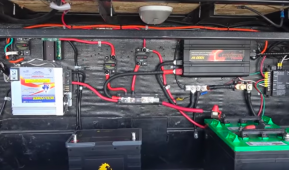
Screen Shot 2021-09-06 at 10.08.38 PM.png
 
Bus bars are distribution blocks to combine / carry voltage and current.

They can be used to distribute negative and ground runs. They can be used to bridge connections on batteries, or combine several connections into a single point on a wall.

As for linear paths, they are used to centralize several connections and cables must be ran to this connection / combining location.

Schematically things might appear linear, but logically routing cables so they don't just cross willy-nilly takes some clever routing and it isn't always as pretty as we would like. Bus bars inherently help with that.

So how do you prevent voltage coming from the solar panels from just jumping straight over to the inverter, bypassing the batteries altogether?

Generally the voltage from solar panels is routed through a Solar Charge Controller - SCC. This regulates the charging of the batteries. Is there a reason you prefer to NOT have the solar panels connected to batteries and go straight to an inverter?


.
 
Last edited:
Generally the voltage from solar panels is routed through a Solar Charge Controller - SCC.
As I mentioned in the previous sentence, and as depicted in the photo, the SCC, inverter and battery are all connected via bus bar (and fuse, in the photo). So what prevents power from going from SCC directly to the inverter?
 
As I mentioned in the previous sentence, and as depicted in the photo, the SCC, inverter and battery are all connected via bus bar (and fuse, in the photo). So what prevents power from going from SCC directly to the inverter?
The current flows wherever the voltage level is lower.

If you batteries are lower - SCC Current flows direction to the battery - if you put a load on the inverter - it's internal resistance rises and thus voltage drops - so the current starts flowing to the Inverter. It's all dynamic.

In a battery systems you got two way power flow all the time.
OK, so if an inverter is getting power from both the battery and, theoretically, the SCC, at the same time, how does this not damage the inverter?
as long they are matched for the same voltage level why should it damage it?

You SCC is putting out 13-15 V volt - your batterie provides 12-14V The Inverter can probably accept anything from 10 to 18V Look in the manual.
 
The Inverter can probably accept anything from 10 to 18V Look in the manual.
Mine shows 11-15v - so I guess the SCC is putting out a max of over 15v only when equalizing. But this is theoretical - last time I equalized it never exceeded 14.5v or so. So I guess the inverter won't care where the volts are coming from, and use it direct from the SCC or battery or both? Something like that....
 
Mine shows 11-15v - so I guess the SCC is putting out a max of over 15v only when equalizing. But this is theoretical - last time I equalized it never exceeded 14.5v or so. So I guess the inverter won't care where the volts are coming from, and use it direct from the SCC or battery or both? Something like that....
Yes
 
so one would connect a battery bank 'most negative' to the same ground bar as the inverter chassis ground?
If it is an RV and the house system uses a ground to chassis, then yes, you can connect to chassis ground.

If it is something like a truck camper or an RV that doesn't have ground to chassis, my preference is to not ground to chassis and leave system as floating.
 
If it is an RV and the house system uses a ground to chassis, then yes, you can connect to chassis ground.

If it is something like a truck camper or an RV that doesn't have ground to chassis, my preference is to not ground to chassis and leave system as floating.
It's independent of anything factory installed, so I guess it's floating by default. I've been grounding case grounds to the chassis at the rear bumper.
 
It's independent of anything factory installed, so I guess it's floating by default. I've been grounding case grounds to the chassis at the rear bumper.
That's where case grounds should be grounded.

RV's like travel trailers, fifth wheels and truck campers are a special breed. Anywhere a case ground is required, it is always run to the chassis. Usually with bare copper conductors, but not always. At least in my Forest River fifth wheel they are. What's interesting is that the main negative battery terminal is also connected to the chassis. Has been on every trailer I have owned. But nothing that I have seen uses the chassis as a negative connection. Everything is 2 conductor all the way back to the power distribution center. So it is a floating system but ultimately, the chassis is ground. Just never used as a conductor.

I guess the simple way to look at it is positive, negative and ground. The chassis is a third conductor, not the negative terminal. I think the reason they do it this way is when you connect to shore power. The trailer will use the ground from the shore power source. One rule you should never break is bonding any neutral, anywhere on the trailer, to ground or negative.
 
Back
Top