diy solar

diy solar

ENJ Power for Heltec/JK BMS

Hi,

The issue with the app is remote access from anywhere. I can put a phone/tablet in the cabinet and leave the app running and then remotely access the phone from a PC, but anytime you close/disconnect that session you have to re-authenticate on the phone end from what I've seen, unless you know off an app that allows remote access to a phone or tablet without prompting/requiring interaction on that end ever (sounds like a security issue to me). I just want the phone/tablet to be a headless slave device effectively.

Have you tried Teamviewer? It's free for personal use. Good remote access over the internet, can be used via LAN too.

There's also scrcpy, but that would only work on a LAN.

dRdoS7
 
Team viewer requires input on the phone end to work and the instant you close that session you need to re-authenticate next time.

So I'd effectively have to connect a session on a machine and leave it running 24/7 so I could then remote access that machine to see the BMS when I wanted to so my disconnection didn't trigger a re-authentication.
 
Hi,

Team viewer requires input on the phone end to work and the instant you close that session you need to re-authenticate next time.

So I'd effectively have to connect a session on a machine and leave it running 24/7 so I could then remote access that machine to see the BMS when I wanted to so my disconnection didn't trigger a re-authentication.

I haven't needed to do anything on the phone, once TV was installed and running. I use it on a 10" tablet as well. Only time it doesn't work is when the phone's gone flat.:oops:

Did you install TV Host?

dRdoS7
 
Last edited:
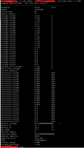
Found a better way and saved myself a handful of RS485 adapters whilst I was at it... as i mentioned earlier jblance publishes a python program on github and I managed to get it to work over Bluetooth BLE.
1621270921287.png
Also confirmed I can connect to multiple BMS's "simultaneously" (in separate instances of the app).. next step is for me to install this as a service and push data out to Grafana... Being able to monitor all BMS's and an aggregate of total kWh's over cloud is now looking much more likely!!

I've even captured some of the advanced setting commands which means in theory soon we can also toggle/set parameters remotely and programmatically...Will keep everyone posted as I progress further... ?
 
@DIY-Dan I just ordered the same USB-RS485 converter, so I'll be able to replicate what you have.

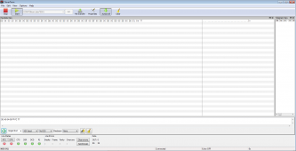
@DIY-Dan - that converter arrived a few days ago and I just had some time to hook it up. I don't have a Win10 install here at the moment, so using an older Win7 that I have in a VM. I used CleverTerm with success, without any special driver or settings:

Screenshot_2021-05-19_15-03-06.png

I also confirmed it works without special requirements on Linux, and works with my Python code without issues.

You sure you have it plugged in in the GPS/RS485 port and not the CAN port, yes? I would also double check the connections again - on mine Yellow is A, White is B and Black is GND. Both GND contacts on the USB converter are fine to use, they're connected.
 
Last edited:
@DIY-Dan - that converter arrived a few days ago and I just had some time to hook it up. I don't have a Win10 install here at the moment, so using an older Win7 that I have in a VM. I used CleverTerm with success, without any special driver or settings:

View attachment 49597

I also confirmed it works without special requirements on Linux, and works with my Python code without issues.

You sure you have it plugged in in the GPS/RS485 port and not the CAN port, yes? I would also double check the connections again - on mine Yellow is A, White is B and Black is GND. Both GND contacts on the USB converter are fine to use, they're connected.
For those who want to use the RS485 connection to the JK line of BMS'

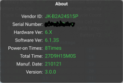
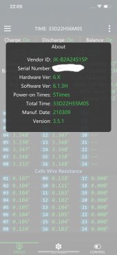
Would anyone with the JK BMS, mine is JK-B2A24S15P, care to show the About box info from the Bluetooth App?

The reason being, that there seems to be a number of differing versions going around with probably different protocols for the RS485.
Mine does not respond to the above code.

Would like to find out which versions work with which protocols.

jkBMS ver.PNG
 
Mine, or at least an old test version that I tried with RS485 today.

screenshot_20201123-222404-jpg.28417
 
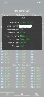
These are the ones that I have
 

Attachments

  • IMG_1318.jpg
    IMG_1318.jpg
    84.2 KB · Views: 11
  • IMG_1319.jpg
    IMG_1319.jpg
    85 KB · Views: 11
Mine, or at least an old test version that I tried with RS485 today.

screenshot_20201123-222404-jpg.28417
Thank you.
So this one as you say, is an older version and works with that protocol.
Mine seems a later version and does not work with that protocol.
Which protocol document are you referencing?
 
So this one as you say, is an older version and works with that protocol.
Mine seems a later version and does not work with that protocol.
Which protocol document are you referencing?

There are two distinct protocols: one for the BMS and one for their Balancer (without BMS). You can find the ones I used here:


The Protocol English Version.pdf is the one that works with mine. The others are for the balancer, but maybe newer versions support this one on the BMS.
 
(I am also Bramhall45)

Has anyone seen this protocol:

Send, Read ALL: 4E 57 00 13 00 00 00 00 06 03 00 00 00 00 00 00 68 00 00 01 29

1. STX: 4E 57
2. LENGTH: 00 13 = 19 bytes
3. BMS_ID: 00 00 00 00
4. Command: 06, READ_ALL
5. FRAME_SOURCE: 03 PC Host computer
6. TX_TYPE: 00 Read request
7. FRAME INFO: 00 set 00 when command : 06
8. REC_NUM: 00 00 00 00
9. END flag: 68
10. Checksum: 00 00 01 29

This is what my seller IC GOGOGO Store, insists is the correct protocol (sent me yet another protocol document in Chinese).
This does not work either, I get response: 0x00

I have verified that their ttl to RS485 dongle outputs voltages in the acceptable range (A = 1.6V, B = 3.2V).
I have verified my RS485 to USB dongle functions correctly.
The BMS works fine with the ANDROID App over Bluetooth.
JBLANCE/MPP-SOLAR Python program outputs correct values over Bluetooth.
But ALL RS485 protocols so far do not work:

4E 57 00 13 00 00 00 00 06 03 00 00 00 00 00 00 68 00 00 01 29

DD A5 04 00 FF FC 77

55 AA 01 FF 00 00 FF

All with response: 0X00

So I can only deduce that I have yet to find the correct RS485 protocol.
I am trying to get my seller to accept the protocol they sent is not correct and maybe there is another one, but..

So if anyone has an RS485 protocol that works on my version of the BMS, I would be most grateful.
 
Last edited:
Progress, got a response to READ ALL:

4E 57 00 13 00 00 00 00 06 03 00 00 00 00 00 00 68 00 00 01 29
4E 57 01 1B 00 00 00 00 06 00 01
79 2A
01 0E ED
02 0E FA
03 0E F7
04 0E EC
05 0E F8
06 0E FA
07 0E F1
08 0E F8
09 0E E3
0A 0E FA
0B 0E F1
0C 0E FB
0D 0E FB
0E 0E F2
80 00 1D
81 00 1E
82 00 1C
83 14 EF
84 80 D0
85 0F
86 02
87 00 04
89 00 00 00 00
8A 00 0E
8B 00 00
8C 00 07
8E 16 26
8F 10 AE
90 0F D2
91 0F A0
92 00 05
93 0B EA
94 0C 1C
95 00 05
96 01 2C
97 00 07
98 00 03
99 00 05
9A 00 05
9B 0C E4
9C 00 08
9D 01
9E 00 5A
9F 00 46
A0 00 64
A1 00 64
A2 00 14
A3 00 46
A4 00 46
A5 FF EC
A6 FF F6
A7 FF EC
A8 FF F6
A9 0E
AA 00 00 00 0E
AB 01
AC 01
AD 04 11
AE 01
AF 01
B0 00 0A
B1 14
B2 31 32 33 34 35 36 00 00 00 00
B3 00
B4 49 6E 70 75 74 20 55 73
B5 32 31 30 31
B6 00 00 E2 00
B7 48 36 2E 58 5F 5F 53 36 2E 31 2E 33 53 5F 5F
B8 00
B9 00 00 00 00
BA 42 54 33 30 37 32 30 32 30 31 32 30 30 30 30 32 30 30 35 32 31 30 30 31
C0 01
00 00 00 00 68 00 00 54 D1
 
FYI I ended up mapping (almost) all of the request commands from the BLE comms. But it seems to be a completely different protocol with different headers and structure despite being also a JK BMS. I've sent those over to jblance so he can update his program when he's ready.
 
@upnorthandpersonal actually - what I found interesting is the code you linked here (https://diysolarforum.com/threads/o...itoring-and-control-freeware.6662/post-248417) referencing https://github.com/PurpleAlien/jk-bms_grafana/blob/main/data_bms.py vs jblance's version (and what I datalogged), seems to indicate that the JK BMS's run on at least 3 different protocols?

For instance, the purplealien code (that's your project right?) uses serial/ttyusb (RS485 adapter?) and all the commands start with 0xDD 0xA5 header, but unlike everyone else, I'm using BT BLE to connect, initially I assumed the protocol commands will be identical just via a different comms method, but no, BLE's command headers all start with 0xAA 0x55 0x90 0xEB... in the jblance project (url above) he's documented 4 different jk protocols, jk02 and jk04, which appears to all use the above BLE headers, the 0xDD 0xA5 headers are under the jk232 (RS-232?) protocol but in the purplealien project this is referred to as the RS485 protocol? meanwhile jblance has a separate jk485 protocol defined that uses 0x55 0xAA headers which actually match the headers in the RS485 documentation sent by ICGOGO (if you bought from them, which I did).... All the command codes after this header appears different in each of these projects too... am I missing something here? Are they just bitshifted versions of the same thing? It would make no sense for JK to create 3 different communication command/response sets for 3 different connectivity methods!

the datalogs I've captured are all BLE comms so I'm not even sure if those command codes will mean something entirely different on an RS232/RS485 protocol.. I'm actually now quite confused between them all
 
Last edited:
seems to indicate that the JK BMS's run on at least 3 different protocols?

I've come to the same conclusion. I think they used to have a separate one for the BMS and their Balancer, but maybe now they're trying to unify these. It's a mess really, and it's going to take me some time to document it all. I've ordered some more devices to compare protocols and to fins out where the differences are. You're definitely not the only one who's confused...

the purplealien code (that's your project right?)

Yes, that's mine.
 
The little red buttons on the front are the pre-charge circuits connected to the resistor across the battery switches.
 
Back
Top