diy solar

diy solar

ENJ Power for Heltec/JK BMS

I've come to the same conclusion. I think they used to have a separate one for the BMS and their Balancer, but maybe now they're trying to unify these.
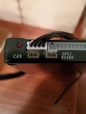
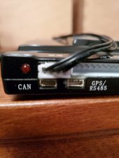
Hmm doesn't look to be the case, in my case it's literally the combined BMS unit with balancer onboard.. The commands I captured over BLE are for the balancer as well as BMS, they share the same request and corresponding response headers for BMS and balancer functions, that seems to be consistent across all the observed protocols.

The binary values of the respective headers are mostly just alternating 0101 or 1010's so maybe the 1st byte is just to tell the BMS whether it's intending to communicate via BLE or RS232/RS485, then the next byte of alternating 0101/1010's is probably just a rudimentary baud rate sync/checksum.

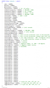
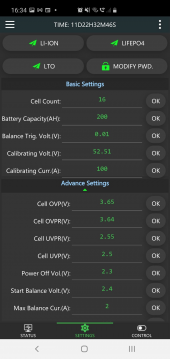
I've attached what I've data logged as the "commands" that the the app sends to the BMS for each of the respective settings in the Advanced menu (whilst the phone app requires a password "123456", this appears to be purely at the app level, that password is not in any of the comms logged)

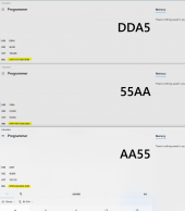
The enum I've coded is in C# so their order is inversed.. eg: getCellData is 0x0096, the actual command is therefore 0x96, 0x00, add header and padding + checksum and it becomes
AA 55 90 EB 96 00 00 00 <pad zeros to 19 bytes> XX
Header
Command
Parameter for the command (if any, have been observed to be always 2 bytes, see comments in code
Checksum (I'm assuming you already know how to calculate this)
Total command string is 20 bytes (fixed).

If the command is successful, the BMS returns
AA 55 90 EB C8 01 01 <pad zeros to 19 bytes> XX
If command is rejected, the bms returns
AA 55 90 EB C8 01 00 <pad zeros to 19 bytes> XX

So it seems the C8 01 is fixed, then the next byte is either true or false for the previous command sent.. There is no reference to the command code in the response itself so if you send multiple commands before you get a response, you wont know what the BMS is responding success/failure to. This is probably why the app does this modally too.

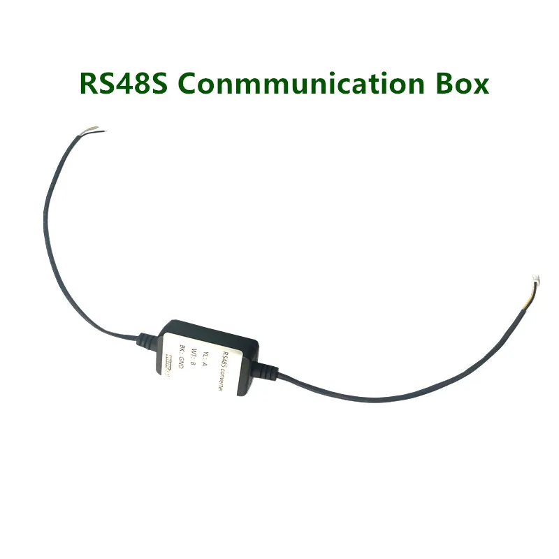
The main advantage I've found with using BLE over RS485 protocol is that, under BT5.0 multipoint connection, I can connect to multiple BMS's simultaneously with a single BT adapter and therefore only use one USB port (or none, if BT is built-in), whereas RS485 will require a dongle purchase for each BMS and I have a few, and I don't have enough USB ports (and don't want to use a hub) because I also need the ports for my inverter.. I've actually written up my own dotnet code to do this because jblance's code creates a connection on each request, gets a single response then closes connection, whereas my own .netcore code can just open the connection, keep the BLE characteristic open and listen for an ongoing stream, and log all of it to influxdb, and only reconnect if a connection is dropped (or the BMS shuts itself lol).
 

Attachments

  • 1623379035131.png
    1623379035131.png
    312.1 KB · Views: 40
  • 1623379265199.png
    1623379265199.png
    77.2 KB · Views: 42
  • 1623379339436.png
    1623379339436.png
    250.1 KB · Views: 39
FYI I ended up mapping (almost) all of the request commands from the BLE comms. But it seems to be a completely different protocol with different headers and structure despite being also a JK BMS. I've sent those over to jblance so he can update his program when he's ready.
Do you happen to be able to send me those dumps?
I'm trying (from 100s of miles away) to change the balancer parameter, but the RS485 instructions (attached) are unspecific which code exactly I have to provide to enable parameter writing ("0x05 Pair code instruction") and it misses an example. I'd hope I could hack this into mppsolar to be able to write a few parameters. In particular I'd be curious about a dump of changing the "Balancer starting value" and also a command to "Enable/Disable" the balancer.

Hints on how to get the RS485 instructions working would also be appreciated. I can actually read single values, just not write them.
 

Attachments

  • BMS.485.instruction.pdf
    700.4 KB · Views: 45
Do you happen to be able to send me those dumps?
I'm trying (from 100s of miles away) to change the balancer parameter, but the RS485 instructions (attached) are unspecific which code exactly I have to provide to enable parameter writing ("0x05 Pair code instruction") and it misses an example. I'd hope I could hack this into mppsolar to be able to write a few parameters. In particular I'd be curious about a dump of changing the "Balancer starting value" and also a command to "Enable/Disable" the balancer.

Hints on how to get the RS485 instructions working would also be appreciated. I can actually read single values, just not write them.
I have a feeling there's a totally different protocol involved here.. What I ended up mapping out was the Bluetooth BLE protocol, which looks VERY different to the official RS485 document the supplier have sent me. Ironically i chose to go the BLE route because BLE supports multi-point connection, that means I can have a single bluetooth adapter on my computer, and talk to 3 JKBMS's simultaneously, and I can dis/connect them remotely without physically walking up to unplug stuff when things go out of whack - as it turns out, it does that every couple of days, the BMS controller just drops out and I would have to reconnect it, at first I thought this was a BLE problem, but my inverters are connected via USB and they also have similar problems (at different times, so i know it's not related).

I'm not sure of the best way to share the BLE mapped commands, i've documented that in code and sent it to jblance who maintains the github project, I'm assuming it's already been included in there somewhere and already documented? aside from that, the C# version of that documentation is in my post a few comments above. That's as far as I got... I wrote my own .NetCore program in C# (but runs off linux) that does the above. At present it's mainly just a monitoring tool that writes data to a database so I can use grafana to map it out
 
Last edited:
Revisiting remote control of this BMS.

I have a Pi4 coming and was looking at Home Assistant and various other things and the critical thing I need is battery percentage and BMS control.

I have not been able to get the RS485 cable to give me anything useful on any platform, but there was talk of BLE adapters etc?

Can you guys provide me with some guidance on what you used and what you've been able to achieve so far?

Thanks in advance :)
I am using solar-assistant.IO, and the Victron 500amp shunt to provide monitoring of SOC across multiple 48V battery banks. It runs on my Pi4, and provides historical and realtime updates. I dont get individual cell voltages, but when I check rhe BMS's via Bluetooth app, I see deltas of around .008v consistent, with the help of the active balancer in the BMS. I set my inverters to 55.4V charge, so they stop charging around 3.45V per cell.
 
I am using solar-assistant.IO, and the Victron 500amp shunt to provide monitoring of SOC across multiple 48V battery banks. It runs on my Pi4, and provides historical and realtime updates. I dont get individual cell voltages, but when I check rhe BMS's via Bluetooth app, I see deltas of around .008v consistent, with the help of the active balancer in the BMS. I set my inverters to 55.4V charge, so they stop charging around 3.45V per cell.
I've looked at this also, a few issues for me.

- They told me It's a custom image that takes up the entire SD card so cannot be run on a Pi with other apps (they said doing so is unsupported and wanted me to just buy a second Pi) If you have done this please let me know.
- What I really want is automation of various smart plugs and my power transfer switch (from on grid to off grid) which I need Home Assistant for I think?
- SA is more about monitoring the inverter and which I can already do well enough with Watch Power or SmartESS, what I really want to see is battery SoC so I can make decisions based on it, which I guess a shunt will give me. I don't generally change BMS settings as it's set nicely (similar to yours) and the pack has done a good 90 cycles now so I'm comfortable with how it's behaving.

A couple questions for you though.

- Is SA allowing you to control the BMS at all or just monitor it?
- Is there any intelligence in SA for controlling smart switches or doing any automation?
- Did you play with the virtual BMS feature? A friend told me he was using it and it was accurately indicating SoC without a shunt, saying it was using Coulomb counting but he was using VRLA cells, not Lifepo4 which is what I use. As I understand it, you can use voltage for SoC with VRLA meaning the virtual BMS might just be using a voltage reading from the inverter , I wasn't sure if SA was smart enough to calculate AH in and out itself.
I will take these one at a time.

-Control vs monitor of BMS. Monitor Only, but the smart shunt connection gives me accurate SOC across my banks, so I know what I have available at all times. It integrates directly with the shunt over the Ve bus to USB cable.
-Any intelligence for controlling switches. No idea, as I have no need to so that.
-Virtual BMS. Did not play with that either, as the Victron shunt connection works fine.
I will be testing the Seplos 200amp BMS's with the Lishen 280's to see if the LV6548's will talk direct Pylontech protocol with the BMS CAN connection. If so, the Inverters themselves will have direct SOC knowledge, so no need for BMS monitoring.
 
Thanks for the info.

I'm thinking adding a smart shunt might be the best step forward IF it will integrate with HA, I'll have a search for what works on that front.

That way I can run HA, get my automation and have accurate SoC data to do the automation want.

Also means avoiding needing a second Pi and SA all together.
It does. Take a look at DMI inc on youtube. He swapped out Grafana with HA, and has his JK BMS's monitoring all his cells with it. He uses Jblance's Github code.

 
Assume it's this?


I still have an issue seeing any data from the JK RS485 cable so I'll watch the video and see what they are doing there.
Yup. Thats the code. You can subscribe and ask questions of the contributors directly. It is very active. I get about 5 or 6 updates a day.
I have it running on another Pi4, and am trying to teach myself python, but had an issue with getting the database running, so I just bought Solar-assistant download and imaged that onto my other Pi4.
I was going to restart my efforts, but then @houseofancients said he was able to get the Seplos BMS working with MPP, so I am going that direction now. Just spent about $7K on Seplos stuff. Sure hope it works!
 
Thanks for the info.

I'm thinking adding a smart shunt might be the best step forward IF it will integrate with HA, I'll have a search for what works on that front.

That way I can run HA, get my automation and have accurate SoC data to do the automation want.

Also means avoiding needing a second Pi and SA all together.
I’m currently using solarassistant.io and it integrates well with HA via MQTT.
 
Yup. Thats the code. You can subscribe and ask questions of the contributors directly. It is very active. I get about 5 or 6 updates a day.
I have it running on another Pi4, and am trying to teach myself python, but had an issue with getting the database running, so I just bought Solar-assistant download and imaged that onto my other Pi4.
I was going to restart my efforts, but then @houseofancients said he was able to get the Seplos BMS working with MPP, so I am going that direction now. Just spent about $7K on Seplos stuff. Sure hope it works!
I have a DEYE inverter and it works perfect with the Seplos BMS via CAN.
 
Assume it's this?


I still have an issue seeing any data from the JK RS485 cable so I'll watch the video and see what they are doing there.
Does anyone know where to get a cable for the tiny CAN and RS485 connectors on the JK/ Heltec BMS? That connector is very small, and the cable needs to go to an RJ type Ethernet connector on the other side. Is everyone making their own cables? The BMS does not come with those cables, an I have not been able to find a source.
 

Attachments

  • 20210925_205147.jpg
    20210925_205147.jpg
    67.5 KB · Views: 8
  • 20210925_205121.jpg
    20210925_205121.jpg
    93.8 KB · Views: 7

You can probably contact them for the CAN side as well. The connector itself is a JST XHP if I remember correctly.
Wow, they are selling my 200amp BMS now for $42 more than I paid, and thats without shipping!
Thanks for the link. Looks like I need to build my own with that tiny connector on one end, and an RJ45 on the other.
 
Back
Top