There are several vendors - you can definitely get it cheaper with some other vendors. Also, there is a 300A version which I really want to try to max outWow, they are selling my 200amp BMS now for $42 more than I paid, and thats without shipping!
Thanks for the link. Looks like I need to build my own with that tiny connector on one end, and an RJ45 on the other.
You are using an out of date browser. It may not display this or other websites correctly.
You should upgrade or use an alternative browser.
You should upgrade or use an alternative browser.
ENJ Power for Heltec/JK BMS
- Thread starter UV-PWRD
- Start date
Sanwizard
Solar Wizard
- Joined
- Feb 2, 2021
- Messages
- 2,714
I bought mine direct from Heltec ( Michelle Duan).There are several vendors - you can definitely get it cheaper with some other vendors. Also, there is a 300A version which I really want to try to max out
Home Assistant up and running so I will start playing with BLE and the JK soon.
I had an interesting "issue" over the weekend though where the BMS noted LVD on a single cell but then 4mins later was fine again (the pack was a good 60% full and that cell was not showing any other issues).
This coincided directly with the both arrays coming online, so large open circuit voltages (340-350v each), but no actual output from them yet, first light of morning.
At this time, when the BMS said LVD on one cell, the inverter logged only 38v from the pack, which was at 52.8v prior to this, then a few mins later, pack voltage was back to 52.8v according to the inverter and every thing was happy again.
I only noticed because I now have a remotely controlled contactors setup to switch between my on and off grid systems and I heard them switch and then switch back - they are mechanically and electronically interlocked so if the off grid system goes down for any reason it will fail over.
I rebooted the BMS, checked the balance wire and it's fine been since (2 days ago).
I notice though that each time I reboot the BMS, the cell balance wire lead resistance values are climbing. Is there an underlying issue here? All connections look good.
Should we be rebooting the BMS every so often etc? System has been live since March and is nearing 100 cycles of the pack, BMS is rebooted only as needed, so not often or regular.
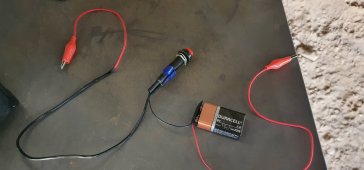
As an aside, I made this for restarting the BMS, works a treat. I have a similar setup with a wire wound ceramic resistor to pre-charge inverter caps for a cold Inverter boot.

Hi, has anyone try to find RX/TX pins in the bluetooth module inside JK BMS???? Probably we could connect an ESP8266 or ESP32 to work as a serial/wifi converter, so the signal doesnt need to converter from RS232 to RS485 (inside BMS) and then RS485 to RS232 and USB outside.
I don't know if it is possible to solder two wires (RX/TX) + GND and keep bluetooth also working.
I don't know if it is possible to solder two wires (RX/TX) + GND and keep bluetooth also working.
Hi, has anyone try to find RX/TX pins in the bluetooth module inside JK BMS???? Probably we could connect an ESP8266 or ESP32 to work as a serial/wifi converter, so the signal doesnt need to converter from RS232 to RS485 (inside BMS) and then RS485 to RS232 and USB outside.
I don't know if it is possible to solder two wires (RX/TX) + GND and keep bluetooth also working.
Should be feasible; I took one apart an posted pictures here:

JBD/Overkill vs JK/Heltec BMS
Has anyone done a comparison between the JBD and JK BMS's? They look very similar to me. The JBD seems to use the Xioxiang app, and the JK uses thr ENJpower app. The apps are also VERY similar. I know Overkill is JBD, ans Heltec is JK based. Is the same manufacturer making both? I am not as...
If I have time I'll have a look.
Edit: this is the module; pin descriptions on one of the pictures:
Well, here is a new one. I need to check where I got them from, but I have a JK-BD6A20S10P, hardware version 6.x, software version 6.0.9S. Date of manufacture: 2020-12-21. Nothing different with the BT app and communication over BT with the jkbms command from the mpp-solar repo.
I attached the RS485 communication cable to it and noticed my usual commands didn't do anything. Just in case, I started playing with different baud rates, and got a response with 115200. The read all command is a familiar one:
However the response is completely different:
I made sure it's not a fluke by changing the checksum in the command, and sending different strings, but it only responds to this and consistently so. I haven't found anything relevant to this response sequence just yet, so might have to spend some time decoding this one...
I attached the RS485 communication cable to it and noticed my usual commands didn't do anything. Just in case, I started playing with different baud rates, and got a response with 115200. The read all command is a familiar one:
4E 57 00 13 00 00 00 00 06 03 00 00 00 00 00 00 68 00 00 01 29
However the response is completely different:
ef 80 80 80 80 80 87 80 e0 7f 0f 80 80 83 80 80
30 80 86 80 80 18 80 87 80 80 18 80 8c 80 80 63
80 8f 80 80 0c 80 8e 80 80 0c 80 8f 80 80 0c 80
98 80 80 c0 80 e7 70 36 80 3e 80 80 c6 1b 7e 80
c7 83 1c 80 73 80 80 80 cf 80 98 0e 80 ce 80 8c
cf 9f c0 0e 06 d8 8f 98 f6 8c 6f 07 f8 f7 bc de
8c 07 d8 1f be 07 f6 dc 60 ef 80 67 07 9f 7f fe
de 80 8f 1f df 80 ff 07 e7 f0 80 f6 7c f6 f3 80
9e 3e e7 f6 80 e7 ff fe f7 ff ff fe fc ff 7f f6
80 80 80 bc 80 fe 80 18 f6 e0 60 80 8f 7e b6 6e
f7 37 ff fb 03 80 80 80 3f fe 7b f8 fe b0 ff bb
b8 6e b7 80 80 80 80 ec bf bf fc bf fb c3 fb ef
df 80 80 80 80 fc 80 80 be ee
I made sure it's not a fluke by changing the checksum in the command, and sending different strings, but it only responds to this and consistently so. I haven't found anything relevant to this response sequence just yet, so might have to spend some time decoding this one...
Sanwizard
Solar Wizard
- Joined
- Feb 2, 2021
- Messages
- 2,714
Interesting! Are you connected to the can or RS port, what is your pinout? John Blance may be able to assist on github.Well, here is a new one. I need to check where I got them from, but I have a JK-BD6A20S10P, hardware version 6.x, software version 6.0.9S. Date of manufacture: 2020-12-21. Nothing different with the BT app and communication over BT with the jkbms command from the mpp-solar repo.
I attached the RS485 communication cable to it and noticed my usual commands didn't do anything. Just in case, I started playing with different baud rates, and got a response with 115200. The read all command is a familiar one:
However the response is completely different:
I made sure it's not a fluke by changing the checksum in the command, and sending different strings, but it only responds to this and consistently so. I haven't found anything relevant to this response sequence just yet, so might have to spend some time decoding this one...
Sanwizard
Solar Wizard
- Joined
- Feb 2, 2021
- Messages
- 2,714
His github folder: jblance/mpp-solarInteresting! Are you connected to the can or RS port, what is your pinout? John Blance may be able to assist on github.
Connected on the RS-485 port yes, same pinout as others, and using the Heltec RS485 converter dongle. I'm starting to think there are some devices on the market that have some custom firmware, maybe from a canceled project or something.
So I just got a new one of these from Hankzor (pictures here) and tried the RS-485 connection again. No response to the read all command at 9600 Baud, however the same response as I have in #87 on 115200 Baud...
so the display is giving you data but you cannot get data out of the RS-485 port?So I just got a new one of these from Hankzor (pictures here) and tried the RS-485 connection again. No response to the read all command at 9600 Baud, however the same response as I have in #87 on 115200 Baud...
I am still waiting for my BMS to come back to me from being sent for repair, only so I can change the commercial invoice value and send it back again... I've been without it for months but bought a 5a Heltec balancer to help keep things happy (so far so good).
I have the inverter and a bunch of other things in Home Assistant now and it would be great to have BMS data in there as well.
so the display is giving you data but you cannot get data out of the RS-485 port?
Yes - I get some kind of data out, but it's not something I've seen documented anywhere.
Ok, progress. Got rid of the RS-485 converter dongle and connected directly to a TTL to USB serial converter. Now I have the correct format.
I have an older set of dongles, and my guess is there have been some changes in that...
I have an older set of dongles, and my guess is there have been some changes in that...
Ooooh i was curious about that! So u got it working? I never bought the RS485 module and have always just used BLE. I was the one who captured all the BLE packets for Jblance so I've been using it in production for more than a year now.Ok, progress. Got rid of the RS-485 converter dongle and connected directly to a TTL to USB serial converter. Now I have the correct format.
I have an older set of dongles, and my guess is there have been some changes in that...
But recently I'm having BLE instability issues and was thinking about trying a wired solution instead, BLE appears to drop off when the BMS is hot, i was using all 200A output and it disconnected itself whilst the BMS is still running, when it cooled down BLE was back online again.
Yeah, the reason it didn't work before is because the baudrate in the BMS was changed from 9600 to 115200 in newer models, but the RS485 converter module itself also has a micro in it, and would obviously not work properly since it expected 9600 unless you also buy a newer version of that... So I got rid of that and just did TTL to USB directly. Works perfectly fine and saves one from having to buy those converter modules.
My GitHub repo, just in case (contains the connector diagram in the readme):

 github.com
My GitHub repo, just in case (contains the connector diagram in the readme):
GitHub - PurpleAlien/jk-bms_grafana: Read data from a JK BMS and graph it in Grafana
Read data from a JK BMS and graph it in Grafana. Contribute to PurpleAlien/jk-bms_grafana development by creating an account on GitHub.
Ahh perfect! I have a couple of spare ESP8266's lying around so I might even see if i can use the GPIO pins directly against the BMS's port.
Are you also having the same reliability issues as I have though? I was pushing 150A+ continuous discharge through my 200A BMS (but for like an hour straight), probably barely staying within the BMS's temp limits but likely exceeded temp of the BT chip? but I can't confirm if TTL would still be responding under those circumstances. If TTL still responds under those conditions then it's a compelling use case for me to switch from wireless to wired, because you don't want to suddenly lose visibility of your battery bank's SoC when it's dumping that much current.
Are you also having the same reliability issues as I have though? I was pushing 150A+ continuous discharge through my 200A BMS (but for like an hour straight), probably barely staying within the BMS's temp limits but likely exceeded temp of the BT chip? but I can't confirm if TTL would still be responding under those circumstances. If TTL still responds under those conditions then it's a compelling use case for me to switch from wireless to wired, because you don't want to suddenly lose visibility of your battery bank's SoC when it's dumping that much current.
daniel32768
New Member
- Joined
- May 13, 2022
- Messages
- 3
Hello everyone ! This is my 1st post on DIY Solar Forum.
I am getting the solar hype (i bet y'all know how it feels like) on my little weekend house (15km away from my apartment - still prefer the apartment - house is smaller in interior space).
I got 4KW worth of solar panels, PIP 11KW max inverter (wanted most powerful single phase all-in-one inverter that i could get my hands on), and 16x EVE LF280K LiFePO4 cells (~ 14KW) , ofc accompanied by JK BMS - the almost perfect BMS out there ( JK - B2A24S20P ).
I am completely off the grid as of now (Grid breaker is off - inverter was pulling 35W at night for no reason (priority - SBU) and rest from batt).
And now ofc comes the desire to monitor everything remotely.
I got a RPi 4 connected via USB with the inverter - with SolarAssistant installed on it - very nice for the inverter side of the data.
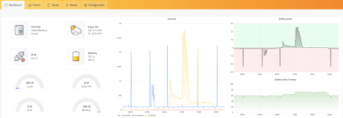
And since JK BMS is not supported yet by them (i am emailing back and forth trying to convince them to implement it - even pointed them to the python BLE library that wirelessly talks to it - we'll see if they finally do it).
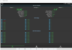
For now i got an old android 5 tablet with remote software (AirDroid) and last version of JK-BMS that still works on Android 5 ( 4.2.0 ) and it does the trick ... but only accessible from PC. I connect with anydesk to my PC when i am away - to see the airdroid window connected to the tablet ?.
Fiddly but it works ...
I'd love grabbing the raw data with the other RaspBerry pi (v3) i have laying around and put it in a grafana.
Congrats for the packet capturing - i bow to you in the name of community.
Regarding the temperatures - i feel like the wires are what is causing it - 2 x 8 AWG is around ~ 20 mm2 of chinese silvery conductor with thin strands and insufficient for the rated 200A
I bought a second bms (just to mod it - FOR NOW) that i intend to use for 2nd battery bank in the autumn when i'll start heating with electricity.
I intend to de-solder original bms wires and solder 2 x 25mm2 ( 4 AWG) and i hope bms will stay cold - this will most likely fix your issue too @lonertic
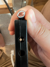
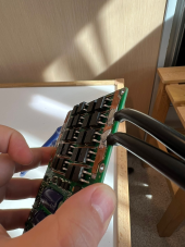
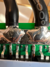
I will have to enlarge case holes and pcb cutoffs for it, but i think it will worth it ... i will replace the current BMS and find out.
If you wish i will post here as well with the results.
Then i will want to do the BLE monitoring one way or the other.
Sorry for the huge post i still feel like i barely scratched the surface about everything i went through (i managed to disbalance the cells but then i balanced them back without taking the pack apart)
I wish you all lots of sun and perfectly balanced cells !
Daniel.
I am getting the solar hype (i bet y'all know how it feels like) on my little weekend house (15km away from my apartment - still prefer the apartment - house is smaller in interior space).
I got 4KW worth of solar panels, PIP 11KW max inverter (wanted most powerful single phase all-in-one inverter that i could get my hands on), and 16x EVE LF280K LiFePO4 cells (~ 14KW) , ofc accompanied by JK BMS - the almost perfect BMS out there ( JK - B2A24S20P ).
I am completely off the grid as of now (Grid breaker is off - inverter was pulling 35W at night for no reason (priority - SBU) and rest from batt).
And now ofc comes the desire to monitor everything remotely.
I got a RPi 4 connected via USB with the inverter - with SolarAssistant installed on it - very nice for the inverter side of the data.

And since JK BMS is not supported yet by them (i am emailing back and forth trying to convince them to implement it - even pointed them to the python BLE library that wirelessly talks to it - we'll see if they finally do it).
For now i got an old android 5 tablet with remote software (AirDroid) and last version of JK-BMS that still works on Android 5 ( 4.2.0 ) and it does the trick ... but only accessible from PC. I connect with anydesk to my PC when i am away - to see the airdroid window connected to the tablet ?.
Fiddly but it works ...
I'd love grabbing the raw data with the other RaspBerry pi (v3) i have laying around and put it in a grafana.

Holy Moly 200A ... i got to 8kw max - pulling 160A while testing everything and bms and wires got hot to the touch ( > 60 deg C ). I did not dare push it further.Ooooh i was curious about that! So u got it working? I never bought the RS485 module and have always just used BLE. I was the one who captured all the BLE packets for Jblance so I've been using it in production for more than a year now.
But recently I'm having BLE instability issues and was thinking about trying a wired solution instead, BLE appears to drop off when the BMS is hot, i was using all 200A output and it disconnected itself whilst the BMS is still running, when it cooled down BLE was back online again.
Congrats for the packet capturing - i bow to you in the name of community.
Regarding the temperatures - i feel like the wires are what is causing it - 2 x 8 AWG is around ~ 20 mm2 of chinese silvery conductor with thin strands and insufficient for the rated 200A
I bought a second bms (just to mod it - FOR NOW) that i intend to use for 2nd battery bank in the autumn when i'll start heating with electricity.
I intend to de-solder original bms wires and solder 2 x 25mm2 ( 4 AWG) and i hope bms will stay cold - this will most likely fix your issue too @lonertic


I will have to enlarge case holes and pcb cutoffs for it, but i think it will worth it ... i will replace the current BMS and find out.
If you wish i will post here as well with the results.
Then i will want to do the BLE monitoring one way or the other.
Sorry for the huge post i still feel like i barely scratched the surface about everything i went through (i managed to disbalance the cells but then i balanced them back without taking the pack apart)
I wish you all lots of sun and perfectly balanced cells !
Daniel.
And since JK BMS is not supported yet by them (i am emailing back and forth trying to convince them to implement it - even pointed them to the python BLE library that wirelessly talks to it - we'll see if they finally do it).
That's why I wish it was open source. I could add support for it. That said, I'm happy using Grafana to do all the monitoring - it's much more flexible anyway.
Nami
New Member
- Joined
- Jan 13, 2022
- Messages
- 153
Hardware Ver after 6.X used 115200 Baud rate of RS485Mine, or at least an old test version that I tried with RS485 today.

Hardware Ver before 6.X used 9600 Baud rate of RS485
Similar threads
- Replies
- 9
- Views
- 357
- Replies
- 8
- Views
- 392
- Replies
- 1K
- Views
- 24K
- Replies
- 10
- Views
- 226


