What BMS are you using? Brand and model?
A 0.6 volt drop is likely a forward biased diode. That could very well be the BMS being in a charge stop mode. Think of it as 2 switches in series. But each switch has a diode across it. If both switches are closed you will get a very low resistance path in both directions. If one switch opens, it is then leaving a diode that will allow current in one direction, but with a 0.6 volt drop, and no more current in the other direction. When the cell voltage is too low, it blocks the load current, but will still allow charging through the diode. If the cell voltage goes too high, it will open the other switch which leaves a diode so that you can still discharge, with a 0.6 volt drop, but no charge current will flow. If both switches go open, then the diodes are in series in opposite directions, and current will not flow either direction.
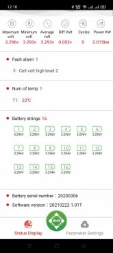
Depending on the type of BMS, there may be a sequence needed to get it to reset. My JK BMS has a very thorough iPhone app. I can set it for the voltages I want, and when the voltage comes back into range, it will auto reset. But I can also manually tell it to stop charge and/or discharge with the app as well. Some other BMS units might require a jumper wire to trigger it into the on mode. You can see Will do that in some of his videos when testing batteries to their limits. You should also check the voltage of each cell. If just one cell is higher or lower than the rest of the bank, that can trip a BMS protection shut off. Many BMS units will only try to balance near full charge, and only while charging. And even then, the balance current may only be 30 milliamps. That can take a LONG time to pull a high cell down to match the others. On the low end of the charge, it can be even worse. One cell can start dropping fast, and the balancing can't do anything about it, so it will just shut off the load until you charge it up.
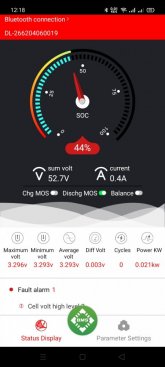
52 volts should be fine on any normal 48 volt battery system. You said this is 16S LFP, so that would be 3.25 volts per cell, that is about 30% charge. That is not so low as to cause a shut down. Can you measure the voltage at the input of the inverter when it cut off? If the BMS is in the charge block mode, the pass diode 0.6 volts you are seeing might not be able to carry full power, and it could be shutting off due to a current limit or heat in that mode. When the voltage at the battery falls to just 48 volts, then you have only 10% remaining and the voltage will start falling fast from there. What is the inverter you are using? In the manual, it should list the low voltage cut out. It should be above 46 volts. If it keeps running below that, you do stand a good chance of the BMS having to shut off, and you do not want that. The BMS should only go into protect shut off if something goes wrong. Your charge controller and inverter should be set to stay within the safe limits of the battery bank.