Chris Youlden
New Member
- Joined
- May 5, 2022
- Messages
- 3
Hi Y'all! Im struggling to get my system working again after installing a new Epever Tracer 50A MPPT. I previously had a Renogy DCC50s combo MPPT/DCDC charger at my controller, but it was underpowered and swapped in the epever (The Renogy is still running and working fine as a DC/DC charger. I believe its a software issue but not entirely sure.
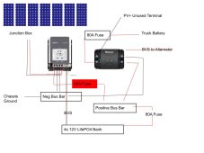
Setup:
6x100W panels on the rooftop on my camper in parallel. No connections have been changed, everything is tight. Plenty of sun. Multimeter reads 20 VOC at the end of the wires (8 gauge and a short run) coming off the roof where they enter the controller. Don't have that positive wire fused or set up with a kill switch, the cheap Amazon inline fuses were getting hot. Checked the diodes on panels and they're fine
Batteries: 4s 12V 280aH Lifepo4 Aliexpress run by a Overkill/xiaoxiang bms.
Controller: 50a Epever Tracer AN. + and - connected to the battery via 2 common busbars. Grounding wire runs to same negative busbar.
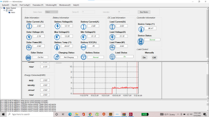
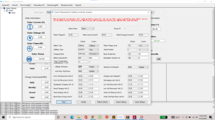
I only pull 2V and 0A as read by the MPPT. Thought maybe it was a reverse polarity issue, but when I switch the + and - solar wires I hear the alarm. The epever is way off with its SOC reading (75% @ 13.14V) but cant see how that would cut out the solar. System was working for about a day (produced 4.3kw) and then no power the next day without any changes to hardware. I've reset the controler by leaving it disconnected, tried with the BVS connected and disconnected. One potential thing I've seen is that when I plug in the MT50 module, it shows at as 48V system on the system info screen but12V (which is what I have)on the device parameter screenScreenshots of software below. Thanks for you help and advice in advance. Cheers!
Setup:
6x100W panels on the rooftop on my camper in parallel. No connections have been changed, everything is tight. Plenty of sun. Multimeter reads 20 VOC at the end of the wires (8 gauge and a short run) coming off the roof where they enter the controller. Don't have that positive wire fused or set up with a kill switch, the cheap Amazon inline fuses were getting hot. Checked the diodes on panels and they're fine
Batteries: 4s 12V 280aH Lifepo4 Aliexpress run by a Overkill/xiaoxiang bms.
Controller: 50a Epever Tracer AN. + and - connected to the battery via 2 common busbars. Grounding wire runs to same negative busbar.
I only pull 2V and 0A as read by the MPPT. Thought maybe it was a reverse polarity issue, but when I switch the + and - solar wires I hear the alarm. The epever is way off with its SOC reading (75% @ 13.14V) but cant see how that would cut out the solar. System was working for about a day (produced 4.3kw) and then no power the next day without any changes to hardware. I've reset the controler by leaving it disconnected, tried with the BVS connected and disconnected. One potential thing I've seen is that when I plug in the MT50 module, it shows at as 48V system on the system info screen but12V (which is what I have)on the device parameter screenScreenshots of software below. Thanks for you help and advice in advance. Cheers!