diy solar

diy solar

Epever Tracer AN series question regarding load terminal

Hogheavenfarm

Regulation Stifles Innovation
Joined
Jun 24, 2022
Messages
432
Here is what I am attempting, maybe its completely out of line, hopefully not -
I want to add a DC 12-24v LED reading lamp to the load terminals of the SCC. (Epever Tracer 6415, I assume most of the AN series is similar).
Pressing the select button on the SCC turns on/off this port, and the MT-50 remote allows me to enter some voltage parameters and such, but no matter what I do, it simply does not work, there is no power to the lamp at all. The manual (SCC) is not clear at all on the port (seems to be #12 on the diagram - front left side port), and the MT-50 remote manual explains a bit more, but changing these seems to have no effect. Has anyone done this and if so, how I can accomplish this? How should I set these parameters? I would like the SCC to turn on this lamp at night (when PV voltage falls below 20v) and off when charging, but trying that setting doesnt activate the light.
 
The MT50 unit overrides the local buttons. Try turning the load ports on via that guy instead of on the scc itself.
I believe I did that, at least with the remote, but I did try pressing the SCC button to turn it on, so I will try the remote as well. I assume I just press the "ok" button on the remote? there is no "enter" button on that.
I was under the impression that setting the remote to turn on the load when PV voltage goes below charging would automatically turn the light on, but it is not doing that.
What I have done (by the remote) -
Set manual load to "on"
set voltage parameters to turn on/off the light when charging stops/starts
set 10 minute delay for both settings
saved both settings.
 
ok, rechecked things, using the remote does not trigger the light, there is an "enter" or "esc" button, really cannot tell which it is, but that does not turn anything on or off like the SCC enter button does. Not sure if "manual load" should be "on" or "off", neither option seems to work.
In the four options for load settings, I have changed 1 (manual load on or off), 2 (PV voltage on/off control (to turn off at 25v, on at 0.00v (it says bad param. for this)) , and 4 (timer settings for on/off , on at 19:00pm off at 6:00am). option 3 is just delay settings, left alone for now. Would like to hear from someone actually using this, how did you do it?
 
Would like to hear from someone actually using this, how did you do it
I’m not using them and haven’t- but plan to so that I can ‘mirror’ the low voltage disconnect of the 120V output from a 1012LV-MK (effectively switching from my fla 12V battery bank to the new LiFePo 12V batteries) using an appropriate amperage relay.

But in programming an Epever 4210, a 6415, another 4215, and a 3210 I programmed them via their laptop/pc application. Because with both the 4210 and 6415 I could not get settings to save reliably but WAS able to save and retain new settings 100% of the time with the laptop.

However, that turning on/off the ‘load’ button doesn’t seem to work regardless I’m thinking either a setting is wrong or iirc there’s an internal fuse in the Epever that might be blown.
 
If you have a voltmeter you can check to see if it's a dry contact output. If so, it will have continuity across the two pins of the load port when it's on and no continuity when it's off.

If it is a dry contact then you wire power into one side and when the load port is on that power will come out the other pin
 
dry contact then you wire power into one side and when the load port is on that power will come out the other pin
True but the Epevers are advertised as being capable of running up to the labeled charge controller output Amps on the load terminals and recording the watts passed.
 
It's a dry contact. You need to apply power to one side.
Not the AN (large chassis) series.
Well that’s interesting to know.
I was thinking probably you saved me a half hour of head scratching when I get to installing my relay voltage controller.

Nevertheless you got me curious because I swear I read in the manual that it was power out up to the labeled charging amps. I have a 4210AN on the wall not connected to anything except a DC breaker.
With the breaker open it gives continuity between batt(-) and load(-) but no continuity on pos(+). Closing the breaker to power the unit, the load switch indeed does power on and off battery voltage without jumpering any power to the pos(+) and there is continuity from batt(+) to load(+) and batt(-) to load(-).

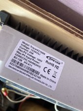
So it is not a dry contact. It provides battery voltage.998C3D36-9064-4416-8DD1-4AB4E308D8CF.jpeg
 
Well that’s interesting to know.
I was thinking probably you saved me a half hour of head scratching when I get to installing my relay voltage controller.

Nevertheless you got me curious because I swear I read in the manual that it was power out up to the labeled charging amps. I have a 4210AN on the wall not connected to anything except a DC breaker.
With the breaker open it gives continuity between batt(-) and load(-) but no continuity on pos(+). Closing the breaker to power the unit, the load switch indeed does power on and off battery voltage without jumpering any power to the pos(+) and there is continuity from batt(+) to load(+) and batt(-) to load(-).

So it is not a dry contact. It provides battery voltage.View attachment 126297

The one in your photo is the smaller chassis charge controller.

This series has a dry contact.

EPEVER 100A MPPT Charge Controller 48V 36V 24V 12V Auto, 100 amp Solar Controller MPPT Negative Ground Max 150V Input fit for Litium Sealed (AGM) Gel Flooded User Battery https://a.co/d/bbXxzT6

Forgive me if I am mixing up models.

I think the OP says he has the 6415 which is to the far right on the product selection menu.
 
Ok. Thank you for clarifying.
Being the one I posted is a 4210AN I didn’t know what to think other than what I measured just now.

OP should here a click in the CC when he turns the load relay on but will not get power out of the contacts (obviously)

OP, are getting a click and is the load showing on on MT-50?

As far as I know, there are no settings that override being able to manually turn the relay on and off at the cc or mt50.
Yes, getting an audible click when the enter button (on the SCC) is pushed, and the SCC (and MT-50) show the "Light bulb" lit and power going to it.
I wired the LED light to the little green receptacle that goes into the front left slot, the LED light says there is no polarity required. So just the two LED wires into the green plug.
I am almost following what you have been discussing, it seems power should be fed in elsewhere and comes out this load slot when the relay clicks? Or maybe I am just not understanding.

Use the two pins on the scc to complete a circuit.
 
If you have a voltmeter you can check to see if it's a dry contact output. If so, it will have continuity across the two pins of the load port when it's on and no continuity when it's off.

If it is a dry contact then you wire power into one side and when the load port is on that power will come out the other pin
This is where I get lost. There are two tiny screws holding the positive and negative wire from the light and that plug is inserted into the front left recept of the SCC. Are you saying I should check for voltage between the two screws when the relay is activated?
 
Not sure of the power requirements - its a 12-24v gooseneck LED reading light, so I think it should be okay in this use. Its made for motorhomes so still within its scope of use.
Can you please show the close up picture of the Load port?
Does it show + and - polarity or C and NO on the Load port?
If it is just simple dry contact then it will not be simple to use it for the load since you will have to have fuse to protect the wire and wire it as shown in post 21 with the added fuse.
 
Last edited:
Back
Top