diy solar

diy solar

EPSolar AN series to RS485 to Ethernet

I only need ~20’ of distance or so and I’ve got recycled Ethernet cable that is at least that long, so I’m trying to understand whether Ethernet cable can be repurposed for RS485 and what’s needed to do that as easily and cheaply as possible…

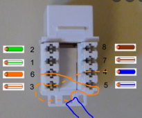
Yes it should work as long as the cable is still good and wired with a straight-thru pinout - as seen in this how-to: making an ethernet cable. (Both ends are wired the same e.g. 568A)

RJ-45_TIA-568A_Right.png


Testing would be pretty straightforward since I could first test whether my new longer cable can successfully replace the 5’ Epever cable in the basement before pulling it through the floor into the living room.

That's a good plan anyway since recycled cable can be damaged in subtle ways that won't show up until you try to use them for actual digital communication.

A lot of folks pull cable through walls without an end on it so it can fit through smaller spaces and not get caught as easily. If you already have RJ45 connectors and the crimper, you can just put an end on temporarily to test with, then cut it off (if needed) to pull the cable through. This loses a couple inches, but may be worth it. Just always remember to leave yourself extra cable in case it takes a couple tries to get a nicely crimped and working connector. :)
 
Yes it should work as long as the cable is still good and wired with a straight-thru pinout - as seen in this how-to: making an ethernet cable. (Both ends are wired the same e.g. 568A)

RJ-45_TIA-568A_Right.png


That's a good plan anyway since recycled cable can be damaged in subtle ways that won't show up until you try to use them for actual digital communication.

A lot of folks pull cable through walls without an end on it so it can fit through smaller spaces and not get caught as easily. If you already have RJ45 connectors and the crimper, you can just put an end on temporarily to test with, then cut it off (if needed) to pull the cable through. This loses a couple inches, but may be worth it. Just always remember to leave yourself extra cable in case it takes a couple tries to get a nicely crimped and working connector. :)
That’s helpful, thanks. So does that mean I can directly plug one of the Ethernet connectors on a standard Ethernet cable into the AN’s RA485 female and as long as I access the correct wires on the other end when converting to USB, all should work?

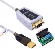
I’m looking at a couple RS485-to-USB adaptors like this:


Or this: https://www.amazon.com/gp/aw/d/B08SM651R9/ref=sspa_mw_detail_0?ie=UTF8&psc=1

With either of these, looks like I just need to cut off the far Ethernet connector and access the correct signals. Once I get it working in the basement, I can just remove the cable from the terminals, push it through the floor, and reconnect the same signals in the living room.

I’m a little lost as to whether I can continue to use the Epever drivers or need to use the drivers than come with these adapters, but the physical side seems straightforward (especially if I can use the existing Ethernet connector on the Epever-end…).
 
I’m trying to understand whether Ethernet cable can be repurposed for RS485
Absolutely.
For short lengths, you can get way just about anything, but twisted pair is recommended (making Cat5 perfect).

You could just use a fully wired ethernet cable, giving Orange-white & Blue on RS485-A and Blue-White & Orange on RS485-B (two pairs for each).
The downside is it will also put 5V (from the SCC) on the cable, which is not protected.

If you have the gear to crimp your own plugs, I'd suggest leaving out the 5V supply.
I don’t have a crimper for Ethernet / RS485 connectors, but I think with one of these I’lol be able to isolate whichever wires I want from the cut end and connect them using the screw terminals:

95F338D6-88AE-4913-826F-81F9E9AA1B60.jpeg
 
That would work.
You could also use a common RJ45 wall socket and only punch down (connect) the four data lines.
Strictly you'd only need two, but:
1. that would leave one pair floating and effectively put the SCC in the middle of a cable twice as long your run (not sure that makes it clear)
2. the OEM USB cable only connects to two of the RJ45 pins, so you'd need to make sure you wired to the matching two of four.

You could also open up the jacket near the SCC plug and cut the conductors you don't want to use (power and one data pair - the ground may as well stay). Then at the top, wire the remaining data pair to two contacts each.

something like this:
1633049727296.png
 
Ah - yes indeed. Forgot about that as I haven't used it in months

View attachment 66826
Check the other setting while you are there, but checking RS-485 should make it work.
I'm trying to attach an original Epever RS-485 to USB connector and have downloaded the USB driver from the Epever web site but I do not see the same port setting screen that you are showing. It doesn't have the RS-485 check box. I've tried it on 2 different Windows 10 pc's and same issue. Have any ideas?
 
Last edited:
Slightly different problem now - I upgraded one SCC giving me a spare to play with. That one was in turn substituted in place of my last remaining PWM reg - then I discovered a problem.
The 1210AN had been maintaining a 24V battery in its original position. When it got moved, it had a 12V battery.
Trouble is I can now not communicate with the SCC to change the voltage setting.

Is there a 'non-rs485' way to reset to factory defaults?
 
Why not? What behavior are you seeing?
No idea 'why'. It was working fine until I moved it, then nothing. On its own display, it looks like its trying, but it's set to 24V (not auto), so just thinks the battery is flat.


As for the behaviour, it 'looks' normal, but no comms out the RS485 port.
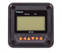
I've tried the MT50, the USB cable and a RS485-Ethernet bridge - nothing.
 
6th attempt to contact epever finally got a reply.
Their suggestion to deal with the 'voltage setting' is the use the front panel and select the User Settings option and set it up that way.

There were no suggestions how to do any kind of reset, and the only the only observation about the lack of comms via RS485 was "perhaps the port is damaged", and asked for photographs.
Further to this: The 'AN' model of SCC's are unable to use older MT-50's from "non-AN" models (due to a protocol issue). Seems silly that they didn't change the model #'s on the 'new' MT-50's though...
 
Further to this: The 'AN' model of SCC's are unable to use older MT-50's from "non-AN" models (due to a protocol issue). Seems silly that they didn't change the model #'s on the 'new' MT-50's though...
Yeah, they did.
The older (RN) SCC speak RS232 and their display is the MT-5
The newer SCC speak RS485 and their display is the MT-50

(RS232 is ok, but only works between two devices. RS485 is more suitable as it allows many devises on a single cable and is suitable for much longer cables)

One thing - don't get caught trying to use the renogy display - they look very similar with the same model numbers, but use a different pinout on the cable.

1658115448861.png1658116347423.png

1658116459944.png
 
Last edited:
I disagree... watch video :


There are 2 identical MT-50 - but apparently different hardware revisions.

Why don't just call him MT-51 or MT-50 b...
 
Ok - that's just dumb.

Now that I've networked all my SCC's, I've put the display aside and it's unlikely to see the light of day again. If you hadn't pointed it out, I probably would have never noticed.
 
Back
Top