diy solar

diy solar

EVE-280 cells should these be clamped tight or spaced for expansion?

I do believe I understand what you are saying, I may not be doing a good job of explaining.

If you have 1 row of cells you have the 660 lbs. 330 lbs on each side, 165 on each rod:
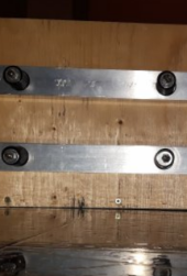
Capture2.PNG

If you have 2 rows of separate cells you would now have 8 springs total. Each separate plate seeing 660 for a total of 1320 lbs:
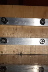
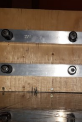
Capture2.PNGCapture2.PNG

You now want to join the plates together and eliminate one of the two rows of springs in the middle but you must maintain the the 1320lbs.
What you have suggested is that you should just average the 1320 over the 6 springs so each would be seeing 220lbs. Why would you do that? That force was in that location for a reason. Why would you all of a sudden decide the outside of the cells need more force simply because you changed the number of springs?
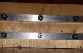

Capture3.PNG

If you left the 4 springs in the middle of the pack you would still average the 1320 over the 8 springs and each would still have 165lbs on each rod. You have now eliminated 2 springs from the middle. The remaining middle two springs need to make up that pressure loss in that location.

As I said in the last post, if you dont think deflection is an issue, you can average out. If that is the case then why even have 6 springs? Just use 4 springs, two on each side that each see 330lbs and call it a day. You still have 1320lbs but I suspect that most people will not think that is such a good idea. Having the middle row helps even out the force. If you are going to go to the trouble of adding the middle row of springs, why not take out any deflection possibility and make the tiny extra effort and simply make sure the force is being applied evenly to each side of each row of cells.

To answer you question directly: Each rod on the outside of the pack would still see 165lbs. The rods that are between cells would need to see double that so 330lbs because they are working acting on two sets of cells, not just one.
 
Last edited:
I will get back to you next year or tomorrow, whichever comes first. Ha Ha
Have a nice evening and Good New Year!
 
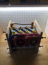
I’ve read a lot of posts/threads about compression. So many ideas and different ways to do it. I ended up using 5/16” aluminum plates with .20” hard rubber matting between plates/cells to give them a “firm” cushion when they expand and rebound when they contract. I used 1/4” threaded rods, 10 rods for each 16s pack, 4 packs of 4 cells, to apply pressure evenly as I could. I used the 12-psi (torque wrench) rule of thumb at 3.25 volts when clamping.
The one thing I never read was how much PSI was gained once you reached 3.65 volts? So tonight, I am charging up a my last 16s pack and had an idea.
When bolting together this pack, I inserted a blood pressure cuff between the middle cells on the end of the pack. I set the blood pressure cuff at 30 mmhg (millimeters of mercury) and started charging. Hopefully this will give me an idea of how much PSI is gained between 3.25v and 3.65v. So for every 1mm of mercury gained, I’ll divide by 51.715 to get the added PSI.
Now I I know this may not be scientific or the best idea ever. But since I was unable to find how much PSI would increase this was the best idea I could come up with to give me a good rule of thumb on the PSI gained.
Thoughts? Does anyone already know this? I assume each application may be different based on the materials used in the compression application.
I just finished reading this thread (starting at post #195, where information from EVE was just coming in). I was excited to see this particular test quoted above, but never saw any results. My comments for anyone who would like to repeat it (I would do it, but I don't have my cells yet) (e.g. how I would do it):
Note: 12 PSI = 620.5 mm Hg, which is probably higher than a BP cuff gauge will go.
Note: 30 mm Hg = 0.58 PSI, which is well under the desired 12 PSI. If you don't start at 12 PSI, you wasted your time.
  1. Put the cells in a rigid frame (wood blocks and pipe clamps, etc.) with the BP cuff, inner tube, etc. in between any two cells (perhaps with plywood on either side of the tube) and pump the cuff/tube to 12 PSI (620.5 mmHg).
  2. You now know you have 12 PSI on the cells. Yes, it is that simple.
  3. Leave everything like it is with 12 PSI on it and charge the cells.
  4. Read the resulting pressure on the pressure gauge after the cells are charged.
If anyone happens to want to do it, I'd love to see the results.

I really like the way that EVE does it in their welded boxes, which is:
  1. Put foam/rubber sheets between each cell.
  2. Compress the pack to 12 PSI.
  3. Clamp (weld) the pack while the pressure is applied.
  4. Release the fixture and the pack remains at 12 PSI inside the case.
Obviously, EVE has done their homework and is using foam or rubber with enough compliance to still have some thickness after compression. I suspect that if you just pack the cells without foam and then clamp them, you may exceed the magic 18 PSI compression as the cells expand.
 
Wouldn’t the BP cuff have to be the same surface area as the side of the cells to equal 12psi? if smaller you would not get 12 psi on the side of the cell unless you pumped the cuff higher to compensate for less square inches.
 
Wouldn’t the BP cuff have to be the same surface area as the side of the cells to equal 12psi? if smaller you would not get 12 psi on the side of the cell unless you pumped the cuff higher to compensate for less square inches.
If you put the cuff between two pieces of plywood, they will distribute the force to the entire face of the cells next to it. 12 PSI is 12 PSI. No need to compensate anything since the measurement is already normalized for you.
 
12 PSI is 12 PSI. No need to compensate anything since the measurement is already normalized for you.
Im afraid you are mistaken. Not in the 12psi = 12psi but in that sticking any arbitrary sized air bladder in between a piece of plywood will result in what you are looking for if you just give it 12psi.

You want 300kg of force acting on the side of the cell. It was worked out that that equates to 12psi acting on the entire surface of the cell. If you have 12 psi acting on only half of the cell you will only have 150 kg of force.

The size of the bladder matters.
Hmmmmm. It turns out that the volume of the bladder matters as well. An inner tube or balloon won't work because it will just change volume if you squeeze it without constraining the volume to the same size. A BP cuff is generally constrained by a cloth outer shell, so perhaps it could still work if folded to the correct size. Hmmmmm.

As for the 300kg of force, I am sure that we really are looking for a normalized 12 PSI uniformly applied against the side of the cell. For the 280AH cells considered in this thread, that comes out (with a units change after the multiplication) to 300kg force. In other words, the 12 PSI is probably applicable to any cell built with this technology, but 300kg applies to only this case size. I'm pointing this out so that somebody doesn't go off and use 300kg to calculate the pressure needed for a 50ah cell.
 
I do believe I understand what you are saying, I may not be doing a good job of explaining.

If you have 1 row of cells you have the 660 lbs. 330 lbs on each side, 165 on each rod:

View attachment 77824

If you have 2 rows of separate cells you would now have 8 springs total. Each separate plate seeing 660 for a total of 1320 lbs:

View attachment 77826View attachment 77827

You now want to join the plates together and eliminate one of the two rows of springs in the middle but you must maintain the the 1320lbs.
What you have suggested is that you should just average the 1320 over the 6 springs so each would be seeing 220lbs. Why would you do that? That force was in that location for a reason. Why would you all of a sudden decide the outside of the cells need more force simply because you changed the number of springs?


View attachment 77825

If you left the 4 springs in the middle of the pack you would still average the 1320 over the 8 springs and each would still have 165lbs on each rod. You have now eliminated 2 springs from the middle. The remaining middle two springs need to make up that pressure loss in that location.

As I said in the last post, if you dont think deflection is an issue, you can average out. If that is the case then why even have 6 springs? Just use 4 springs, two on each side that each see 330lbs and call it a day. You still have 1320lbs but I suspect that most people will not think that is such a good idea. Having the middle row helps even out the force. If you are going to go to the trouble of adding the middle row of springs, why not take out any deflection possibility and make the tiny extra effort and simply make sure the force is being applied evenly to each side of each row of cells.

To answer you question directly: Each rod on the outside of the pack would still see 165lbs. The rods that are between cells would need to see double that so 330lbs because they are working acting on two sets of cells, not just one.
Sorry not to get back to you sooner. Seems that this is a rather intractable problem. I have asked
a couple on engineering friends and they also are not sure which way it should be. The answer seems to be that if there is no deflection in the plate either way will work. If there is deflection then evenly distributing the pressures is probably the way to go. If there is more pressure on the middle of the plate and the plate deflects then over time there will be more pressure on those parts of the plate that are deflecting. One of the engineers is going to do a vector diagram to see how that looks..... I am waiting on that.

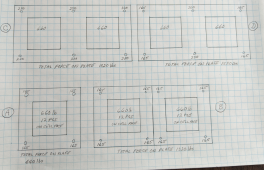
I have attached a couple of drawings for clarity:

A is simply one cell with four bolt/springs applying 660 pounds of force on the cell face
B is illustrating two cells and two plates side by side but not attached to each other
C is one plate covering two cells and having evenly weighted bolt/springs applying force
D is one plate covering two cells and having the combined force of the 4 bolt/springs in the
centre of A replaced with 2 bolt/springs
1641305069735.png


The next drawing is how I am trying to arrange a 48 volt series pack with 16 EVE 280 cells. There will be 4 cells wide by 4 deep, bolt/springs represented by the circles, not to scale. The weights on the bolt/springs to be determined.1641304982051.png
 
"C" is correct so that the forces are distributed as equally as possible across the plate. "D" will try to bend the plate and crush the inner edges of the cells because the force is not equal across the cell.

Think of this as the same as head bolts on a car engine. You torque all of the bolts to the same value, not more on the inside bolts and less on the outside ones.
 
There is also this bit from the EVE datasheet @Steve_S uploaded to the resources section:

View attachment 14253

This chart is creating much mis-interpretation and in my opinion is borderline fraud.

First, it specifies at 1 CA.

What is not directly mentioned is their compression fixture must also be providing cooling for cell. At 1 CA discharge/charge rate the cell internal self heating will be 32 to 40 watts. The cell will get hot with this level of sustained current which will degrade their cycle life if not externally cooled.

Their test is not with multiple prismatic cells packed side by side, reducing the cells ability to dissipate self heating.

At 0.5 CA discharge/charge the internal self heating is about 10-12 watts
At 0.2 CA discharge/charge the internal self heating is about 2.5 watts.

These thick electrode cells are not designed for sustained high cell current above 0.5 CA.

If you don't heat up the cell with sustained high cell current rate, compression should have little benefit. If compression is done with hard, flat, non-complient surface plate it can create high pressure points that can crush through cell's polymer film separators creating cell shorts.
 
Sorry not to get back to you sooner. Seems that this is a rather intractable problem. I have asked
a couple on engineering friends and they also are not sure which way it should be. The answer seems to be that if there is no deflection in the plate either way will work. If there is deflection then evenly distributing the pressures is probably the way to go. If there is more pressure on the middle of the plate and the plate deflects then over time there will be more pressure on those parts of the plate that are deflecting. One of the engineers is going to do a vector diagram to see how that looks..... I am waiting on that.

I have attached a couple of drawings for clarity:

A is simply one cell with four bolt/springs applying 660 pounds of force on the cell face
B is illustrating two cells and two plates side by side but not attached to each other
C is one plate covering two cells and having evenly weighted bolt/springs applying force
D is one plate covering two cells and having the combined force of the 4 bolt/springs in the
centre of A replaced with 2 bolt/springs
View attachment 78280


The next drawing is how I am trying to arrange a 48 volt series pack with 16 EVE 280 cells. There will be 4 cells wide by 4 deep, bolt/springs represented by the circles, not to scale. The weights on the bolt/springs to be determined.View attachment 78279

I'll take E, none of the above. If in the drawings the inside square represents the location of the cell then that's a poor design, in my layman's opinion. For my compression fixture, the rods are about 1" above the bottom of the cells and about 1" below the top of the cells.
 
This chart is creating much mis-interpretation and in my opinion is borderline fraud.

First, it specifies at 1 CA.

What is not directly mentioned is their compression fixture must also be providing cooling for cell. At 1 CA discharge/charge rate the cell internal self heating will be 32 to 40 watts. The cell will get hot with this level of sustained current which will degrade their cycle life if not externally cooled.

Their test is not with multiple prismatic cells packed side by side, reducing the cells ability to dissipate self heating.

At 0.5 CA discharge/charge the internal self heating is about 10-12 watts
At 0.2 CA discharge/charge the internal self heating is about 2.5 watts.

These thick electrode cells are not designed for sustained high cell current above 0.5 CA.

If you don't heat up the cell with sustained high cell current rate, compression should have little benefit. If compression is done with hard, flat, non-complient surface plate it can create high pressure points that can crush through cell's polymer film separators creating cell shorts.
thanks to advice like this and other advice regarding internal self-heating of 300Ah class LiFePO4 cells being discussed,

decided to target 0.3 CA discharge/charge rate for the 12x 302Ah CATL cells on hand. makes the connections much easier for me.

more than 15 Watts of Internal Heating for Continuous Load or Charge will drive Calendar Aging if not dissipated!

100A in or out of 300Ah cell cause ~5W heat PER CELL, which for 4S pack is 20W heater in box.
 
Hmmmmm. It turns out that the volume of the bladder matters as well. An inner tube or balloon won't work because it will just change volume if you squeeze it without constraining the volume to the same size. A BP cuff is generally constrained by a cloth outer shell, so perhaps it could still work if folded to the correct size. Hmmmmm.

Volume of the bladder is irrelevant in so far as it does not effect surface area. In the balloon/innertube, as the volume expands it is increasing surface area therefor force it is applying on the surface. You do not need to fold the cuff, you just need to determine the area of the cuff, the force you want to apply and do the math to figure out how much pressure to put into the cuff to get the desired force.

As for the 300kg of force, I am sure that we really are looking for a normalized 12 PSI uniformly applied against the side of the cell. For the 280AH cells considered in this thread, that comes out (with a units change after the multiplication) to 300kg force. In other words, the 12 PSI is probably applicable to any cell built with this technology, but 300kg applies to only this case size. I'm pointing this out so that somebody doesn't go off and use 300kg to calculate the pressure needed for a 50ah cell.

The published spec was a force in kg not a pressure in psi or kpa and that was for 280ah cells. It was x # of kg on a 280ah cell. That was converted to psi for some reason and has caused a lot of confusion and misunderstanding for a lot of people.

If you want to extrapolate that 300kg of force to a different cell go ahead but it is not necessarily relevant.
 
What is not directly mentioned is their compression fixture must also be providing cooling for cell. At 1 CA discharge/charge rate the cell internal self heating will be 32 to 40 watts. The cell will get hot with this level of sustained current which will degrade their cycle life if not externally cooled.
Wow! 32 to 40 Watts PER CELL!!
4S pack144W internal heating at 1 CA
8S pack288W internal heating at 1 CA
16S pack576W internal heating at 1 CA
Running 1C continuous, that's A LOT OF HEAT TO DISSIPATE! wow. toasty cells.
These thick electrode cells are not designed for sustained high cell current above 0.5 CA.
thank you for mentioning this here and elsewhere. 0.3CA or 100A on a 300Ah cell continuous is the ceiling i'm setting for myself. until i have a robust active thermal management system this just feels appropriate for my goals of long operational lifetime. even with active thermal management, the core of the cell material would still heat up under high sustained load, so i still would not go past 0.5CA continuous. that's still 40W for a 4S pack, much more heat flux than i want to need to dissipate. minimize calendar aging by keeping temperature of cell material between 10-25C.
If you don't heat up the cell with sustained high cell current rate, compression should have little benefit. If compression is done with hard, flat, non-compliant surface plate it can create high pressure points that can crush through cell's polymer film separators creating cell shorts.
interesting, thanks.
due to my targeting max continuous 0.3CA discharge/charge, rigorous compression seems superfluous almost. just want a fixture to keep the cells in place, protect terminals, and prevent terminal disconnection from any vibration.

double reply, but hey, this knowledge about thick electrode cells deserves more light of day imho! :)
 
"C" is correct so that the forces are distributed as equally as possible across the plate. "D" will try to bend the plate and crush the inner edges of the cells because the force is not equal across the cell.

You are having a little difficulty with pressure and force.

Looking at C, You are applying 220 lbs to the outside, on the inside you are applying 220 lbs.

If you weight 200 lbs and take 2 scales side beside side, spaced 2 feet apart and put a board across them. Then stand you 200 lbs in the middle of the board. What does each scale read?

I hope you say 100lbs.

That is what is happening in C. You are applying 220 lbs to the outside because there is only one cell that is seeing the entirety of that load. The 220 you are applying between the cells is being applied to 2 cells so each cell is only seeing 110 lbs. In C the forces being applied to the inside of the cells is a lot lower than the outside where as in D, both inside and outside are seeing 165lbs.

Think of this as the same as head bolts on a car engine. You torque all of the bolts to the same value, not more on the inside bolts and less on the outside ones.

This is completely different and not relevant. The same torque being applied to each bolt has nothing to do with the required clamping force in a given area. It is because that is the working torque that given fastener is designed to tolerate. The engineer has done the work to determine what the maximum load a head stud will be required to resist, finds the head stud that will do that job, specs it and adopts that fasteners torque spec.

It is also not relevant because the forces being applied to a cylinder head is one cylinder at a time where the cell compression is all cells all at the same time.
 
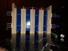
I'll take E, none of the above. If in the drawings the inside square represents the location of the cell then that's a poor design, in my layman's opinion. For my compression fixture, the rods are about 1" above the bottom of the cells and about 1" below the top of the cells.
I placed mine at 1/4 and 3/4 of the way up the cell. I think that is a little closer together than yours. I put mine there so the lower rod acts on the bottom half and the top rod works on the top half. Mind if I ask why you chose the position you did?

20210311_203537.jpg
 
I placed mine at 1/4 and 3/4 of the way up the cell. I think that is a little closer together than yours. I put mine there so the lower rod acts on the bottom half and the top rod works on the top half. Mind if I ask why you chose the position you did?

Because it was symmetrical? Looking at the picture below, my top rod appears to be a bit lower than 1" from the top of the cells. It's hard to tell the distance from the angle the photo was taken.

Battery Compression Frame.jpg
 
Because it was symmetrical?

That's reasonable. With 3/4" plywood, simply having one near the top and one near the bottom has to be "in the ball park". Having them any closer than mine I dont think would be wise but anywhere between where mine are and just up/down from the bottom/top I think is all about equal.

Above and below the cells I dont think is a good idea either.
 
Because it was symmetrical? Looking at the picture below, my top rod appears to be a bit lower than 1" from the top of the cells. It's hard to tell the distance from the angle the photo was taken.

View attachment 78335
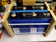
I did mine spaced like yours except with an inch more plywood on the bottom, this allows me to heat or cool the air all the way around the cells as my system is mobile. Four rods with 160 pound die springs puts me slightly below 12 psi on the cells at 50% soc, as they swell it will stay below Armageddon at 17 psi.
 

Attachments

  • 999CBFBA-E802-4554-9323-E2985A2AF94C.jpeg
    999CBFBA-E802-4554-9323-E2985A2AF94C.jpeg
    128.4 KB · Views: 50
This chart is creating much mis-interpretation
Maybe. I don't have the expertise to have a strong opinion with confidence. What I do know, is that chart is one of about 4-6 datapoints I've seen that all point to the same general conclusion, compression of around ~12 psi is optimal for maximum cycle life. Its not just one EVE datasheet or one manufacturer stating this. You may well be right that it is misleading for our application, but I've not seen any data that can confirm or disprove this, have you? If so, I would be very interested to learn more.

What I haven't seen is any test data or manufacturer recommendations that consider compression and C-rate at the same time. EVE's newest 280Ah cell is tested at 0.5C, it would be interesting to check if their compression reccomendation/estimates are the same or different in this newest datasheet LF280K.

Anecdotally, there are many members on the forum that have reported natural swelling and (whatever the opposite of swelling is) at low C-rates with the large aluminum prismatics (EVE, Lishen, etc). This would suggest compression has value even at low C, would it not?

and in my opinion is borderline fraud.
First, it specifies at 1 CA.
That is the rate at which the cells are tested and cycle life ratings are determined for this cell. 1C is not very representative of most of our use cases. But it seems pretty extreme to call that borderline fraud (unless i'm missing your point).

What is not directly mentioned is their compression fixture must also be providing cooling for cell. At 1 CA discharge/charge rate the cell internal self heating will be 32 to 40 watts. The cell will get hot with this level of sustained current which will degrade their cycle life if not externally cooled.

Their test is not with multiple prismatic cells packed side by side, reducing the cells ability to dissipate self heating.

At 0.5 CA discharge/charge the internal self heating is about 10-12 watts
At 0.2 CA discharge/charge the internal self heating is about 2.5 watts.

These thick electrode cells are not designed for sustained high cell current above 0.5 CA.

If you don't heat up the cell with sustained high cell current rate, compression should have little benefit. If compression is done with hard, flat, non-complient surface plate it can create high pressure points that can crush through cell's polymer film separators creating cell shorts.
This (the tradeoff between compression/fixture and cooling at high and low c-rates) is an interesting question, that I have wondered about for some time. My assumption was rather opposite to yours though (and I will fully admit this may be due to ignorance of the details). My pre-existing assumption was that the higher the c-rate the more one might consider preferencing cooling/airflow over compression (since higher C-rate = more heat), and the lower the c-rate (<0.5c) the more clear the case is for compression (simply because there is not a lot of heat generated at low C).

As for these big cells not being designed for high c. I think you are quite right. If you look at Frey ("Fortune") cells, they are specifically designed with an Air Gap, but they are built much more robustly than the large commodity prismatics, and they notably do not make any cell larger than 110Ah and do not have nearly as large a broad side compared with the 280-300Ah cells (they also have a lower/more conservative cycle life. It seems the large aluminum cells are optimized for two things only, low cost, high energy density.

One thing I will point out though, compression or no compression, people are generally building packs the same way. In practice its not a decision between compression and cooling for most people here. The people that aren't using compression are for the most part arranging the pack in the same way, just not with precise compression (i.e. threaded rod but no springs, or tape, etc). Point being, no air gaps one way or the other for most people, with or without compression.

Could you elaborate on what makes you feel that compression is of little to no value at <0.5C and what logic or data that opinion is based on? I believe you understand the principles and the science on a much deeper level than I do so I would very much value your insight.
 
Back
Top