diy solar

diy solar

EVE-280 cells should these be clamped tight or spaced for expansion?

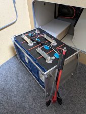
I did mine spaced like yours except with an inch more plywood on the bottom, this allows me to heat or cool the air all the way around the cells as my system is mobile. Four rods with 160 pound die springs puts me slightly below 12 psi on the cells at 50% soc, as they swell it will stay below Armageddon at 17 psi.
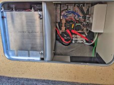
nice kapton tape on conductors, looks like MRBF fuse on positive terminal, and nice flex cable, and nice silicone tube covering threaded rod! thanks for sharing
 
Could you elaborate on what makes you feel that compression is of little to no value at <0.5C and what logic or data that opinion is based on? I believe you understand the principles and the science on a much deeper level than I do so I would very much value your insight.
Compression is intended to suppress delamination, primarily the aluminum and copper foil from their respective LFP and graphite screen printed material. Electrode delamination from metal foil is more likely to happen when there is more temp cycling of cell due to temp expansion coefficient differences with the metal foil. For thick electrode cell design, sustained cell current above 0.5C subjects cell to greater self heating. Thicker electrode printed cell designs are also more vunerable to mechanical shear stress on the electrode material.

These particular cells are made with thick electrodes in the 130 to 150 um thickness range. This is the cake material pasted to metal foil., to yield the greatest AH per volume/weight. AH's sells cells and the cheapest way to get high AH cells is with thick electrodes. AH's does not equate to high peak current capability. High peak current cell design have much thinner electrodes in 40-80 um range.

Thicker electrodes cell design has earlier current induced onset of electrode layer ion starvation when cell is subjected to cell current above approximately 0.5CA

Ion starvation is like a water well head getting starved of surrounding water diffused through soil when too much gallons per minute is extracted from well. For a water well it means more pump power is required to draw in the water from surrounding soil. For a Li-Ion cell it means greater overpotential kinetic energy is required to draw the diffusion of lithium ions through the cell to meet the demanded cell current. This creates greater terminal voltage slump, beyond the normal logarithmic relationship of overpotential voltage to cell current.

Greater overpotental (terminal voltage slump) means more overhead energy is being required to supply demanded cell current which means greater cell losses. More cell losses means greater cell internal heating. Which brings us back to greater temp cycling which stresses the electrodes graphite and LFP binder attached powder cake to the metal foil inducing a greater likelihood of delamination. Cell terminal voltage slump delta to no load equilibrium times the cell current is pretty close to total cell loss and internal self heating.
 
Last edited:
I will provide the link to the post too but for some reason I can't post links from his forum so it won't work. But just in case it does.. here is the link:
What size compression springs?
I don't recall, its not my system, and it's a post I made a little over a year ago. I believe the details are in the linked thread on the other forum.
Link maybe?
The link is in the comment you quoted ;) or at least it shows it is on my end, but I recall there was some weirdness with that link. If it doesn't work, try this plaintext:
https://groups.google.com/forum/m/?...n/electrodacus/pouch/electrodacus/bKIRlxsSLvk
 
I do believe I understand what you are saying, I may not be doing a good job of explaining.

If you have 1 row of cells you have the 660 lbs. 330 lbs on each side, 165 on each rod:

View attachment 77824

If you have 2 rows of separate cells you would now have 8 springs total. Each separate plate seeing 660 for a total of 1320 lbs:

View attachment 77826View attachment 77827

You now want to join the plates together and eliminate one of the two rows of springs in the middle but you must maintain the the 1320lbs.
What you have suggested is that you should just average the 1320 over the 6 springs so each would be seeing 220lbs. Why would you do that? That force was in that location for a reason. Why would you all of a sudden decide the outside of the cells need more force simply because you changed the number of springs?


View attachment 77825

If you left the 4 springs in the middle of the pack you would still average the 1320 over the 8 springs and each would still have 165lbs on each rod. You have now eliminated 2 springs from the middle. The remaining middle two springs need to make up that pressure loss in that location.

As I said in the last post, if you dont think deflection is an issue, you can average out. If that is the case then why even have 6 springs? Just use 4 springs, two on each side that each see 330lbs and call it a day. You still have 1320lbs but I suspect that most people will not think that is such a good idea. Having the middle row helps even out the force. If you are going to go to the trouble of adding the middle row of springs, why not take out any deflection possibility and make the tiny extra effort and simply make sure the force is being applied evenly to each side of each row of cells.

To answer you question directly: Each rod on the outside of the pack would still see 165lbs. The rods that are between cells would need to see double that so 330lbs because they are working acting on two sets of cells, not just one.
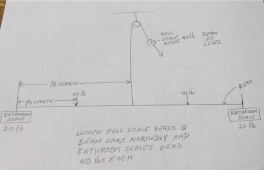
Well it was quite a go around, not getting straight answers so in the end I made a little model with a couple of bathroom scales, a pull scale, some weights, a pulley and some blocks to see what actually happens with the various loads.
noenegdod what you have described is exactly what the scales said: in order to balance out the beam in my drawing I had to pull twice the weight of one side of the
I do believe I understand what you are saying, I may not be doing a good job of explaining.

If you have 1 row of cells you have the 660 lbs. 330 lbs on each side, 165 on each rod:

View attachment 77824

If you have 2 rows of separate cells you would now have 8 springs total. Each separate plate seeing 660 for a total of 1320 lbs:

View attachment 77826View attachment 77827

You now want to join the plates together and eliminate one of the two rows of springs in the middle but you must maintain the the 1320lbs.
What you have suggested is that you should just average the 1320 over the 6 springs so each would be seeing 220lbs. Why would you do that? That force was in that location for a reason. Why would you all of a sudden decide the outside of the cells need more force simply because you changed the number of springs?


View attachment 77825

If you left the 4 springs in the middle of the pack you would still average the 1320 over the 8 springs and each would still have 165lbs on each rod. You have now eliminated 2 springs from the middle. The remaining middle two springs need to make up that pressure loss in that location.

As I said in the last post, if you dont think deflection is an issue, you can average out. If that is the case then why even have 6 springs? Just use 4 springs, two on each side that each see 330lbs and call it a day. You still have 1320lbs but I suspect that most people will not think that is such a good idea. Having the middle row helps even out the force. If you are going to go to the trouble of adding the middle row of springs, why not take out any deflection possibility and make the tiny extra effort and simply make sure the force is being applied evenly to each side of each row of cells.

To answer you question directly: Each rod on the outside of the pack would still see 165lbs. The rods that are between cells would need to see double that so 330lbs because they are working acting on two sets of cells, not just one.
Well it was quite a go around, not getting straight answers so in the end I made a little model with a couple of bathroom scales, a pull scale, some weights, a pulley and some blocks to see what actually happens with the various loads.

noenegdod; What you have described is exactly what the scales said: in order to balance out the beam (ie. make it level) in my drawing I had to lift 40 lb. at the center of the beam and when I did that both of the bathroom scales read 20 lb. When there was no lift in the middle of the beam the beam sagged noticeably and the bathroom scales both read 40 lb. Both ways balance out the 80 lb. of downward force but there must be more of the force concentrated in the middle of the beam when it is not supported as it is deflecting downward. There was no other amount of lift than 40 lb. on the center of the beam that would equalize the forces on the beam. If you divided the three upward forces equally (ie. 26.6 lb. on each bathroom scale and 26.6 lb. on the pull scale) the beam is deflected upward.

In example “C” of post #708; using one plate to compress more than one set of cells and dividing the compression force equally between the number of compression points would result in not compressing the outer edges of the cells enough and the inner edges too much.......if there is deflection in the plate.....and there is almost always some deflection.

I have found this to be a challenging problem to get into words and it seemed to be the same for the people I collaborated with. I am sure someone will come up with a better way to explain what my little experiment showed. Thank you noenegdod for getting this discussion going and on the right track.

1641684818852.png
 
It seems as though there are an infinite number of ways to build a fixture for a 4s 280ah battery.
FWIW this is the approach I took...

PXL_20210427_203323810.jpg

PXL_20210427_003351739-01.jpeg

This battery is for my van camper which I primarily use during the summer to escape the desert heat of southern Arizona. I wanted to be able to easily remove the battery when the van is not in use for the 8 months I spend at my winter home. During the shoulder seasons the temperature in the van regularly exceeds 100 degrees - which is not good for the battery!

Space constraints dictated the design, in particular the overall length. IMHO this design offers some advantages over other approaches. For example: the threaded rod in combination with the binding barrels reduces the overall length and takes some of the guesswork out of 'fixture compression'. The components I used resulted in about the right amount of compression. IE: After the pack is fully assembled you tighten the binding posts all the way, this puts an equal amount of compression on the pack, no need to guess how much torque to apply to the nuts on the threaded rod. If you need more or less compression simply add or remove some washers.

I felt it was important that the threaded rod & binding posts be manufactured with tight tolerances, which I believe these are. It was not necessary to modify the length of the threaded rods. The 8" x 8" aluminum plate works out to be just the right size. So all you need is a hand drill to make the holes in the end plates and a pair of scissors to cut the foam & neoprene separators.

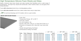
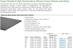
I read somewhere on this thread that Norseal was recommended to use between the cells. The silicone foam I chose had very similar characteristics to what was recommended at about 1/3 the cost. I placed that material between the cells and placed neoprene on the aluminum end plates. The end result is a fairly compact monolithic block that exhibits no lateral flexing or twisting...

Silicone foam comparison:
$25 vs $79 for a 12 x 12 sheet.
Pressure to compress to 25% 7 PSI vs 9 PSI

Screenshot 2022-01-10 12.03.00 PM.png

Screenshot 2022-01-10 12.04.40 PM.png

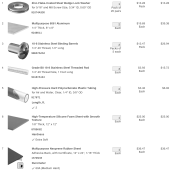
The total cost for this approach is quite high! McMaster Carr sells premium products at a premium price! However - as I said - space constraints forced me to keep the overall length to an absolute minimum. No doubt some of the components could be substituted with something less expensive. I present this BOM as a guide for what to consider when choosing components.


Screenshot 2022-01-10 10.15.14 AM.png
 
Last edited:
In example “C” of post #708; using one plate to compress more than one set of cells and dividing the compression force equally between the number of compression points would result in not compressing the outer edges of the cells enough and the inner edges too much.......if there is deflection in the plate.....and there is almost always some deflection.
This is backwards. The outer edge of each pack would be seeing 440 lbs total (220 x 2) but the inner edges would be seeing 440lbs (220 x 2) but that 440 would be shared between both packs. The inside "edge" of each pack would see a total of 220lbs while the outside is seeing a total of 440lbs. This is the opposite of what is in bold above.
 
This is backwards. The outer edge of each pack would be seeing 440 lbs total (220 x 2) but the inner edges would be seeing 440lbs (220 x 2) but that 440 would be shared between both packs. The inside "edge" of each pack would see a total of 220lbs while the outside is seeing a total of 440lbs. This is the opposite of what is in bold above.
I see that it is backwards, thank you for pointing that out.
 
What I haven't seen is any test data or manufacturer recommendations that consider compression and C-rate at the same time. EVE's newest 280Ah cell is tested at 0.5C, it would be interesting to check if their compression reccomendation/estimates are the same or different in this newest datasheet LF280K.
The LF280K datasheet is available here: https://www.evebattery-germany.de/wp-content/uploads/2021/11/LF280K-Product-Specification.pdf

They still specify a 300 (+/-20) kgf clamp in the cycle rating tests. Thickness is also specified under this clamping force; 72 +/-1 mm for a single cell and 72 +/- 0.5mm average over 200 cells at 30-40% SOC. Also unlike some older datasheets they do not specify a cycle rating without a clamping force.
 
  • Like
Reactions: Dzl
If you do clamp cells together, you best use a compliant spongy pad between cells to prevent high pressure points on cells.

Cell layers wrappings are not uniformly flat. Just aluminum end plates clamping cells together is likely to create very high pressure points on cells' surfaces. Cell separator layers between neg anode and pos cathode electrodes is a thin polymer plastic film with very small, perforated holes to allow lithium ions to pass through. With enough pressure point it can be crushed to the point of creating a short circuit within cell.

This is why I am against DIY'ers clamping cells. What you might gain versus what you might lose is not favorable.
Yeah, I'm on board with that argument. For me personally I'm going to put my bank on a boat, so I do need some kind of secure fixturing and vibration dampening for the cells, and foam of some kind is looking like a pretty good option.
 
The LF280K datasheet ...unlike some older datasheets they do not specify a cycle rating without a clamping force.
And the LF280K Cycle vs. capacity curve with 300kgf clamping force is much more linear than the 2019 version (maybe two versions back?) with clamping force, which actually lost more capacity over the first ~1500 cycles than without any compression "fixture".
 
The LF280K datasheet is available here: https://www.evebattery-germany.de/wp-content/uploads/2021/11/LF280K-Product-Specification.pdf

They still specify a 300 (+/-20) kgf clamp in the cycle rating tests. Thickness is also specified under this clamping force; 72 +/-1 mm for a single cell and 72 +/- 0.5mm average over 200 cells at 30-40% SOC. Also unlike some older datasheets they do not specify a cycle rating without a clamping force.
Let me try to convert… 300kgf (kilogram foot pound) 260 inch pounds or 21.7 foot pound. Correct??
 
If you do clamp cells together, you best use a compliant spongy pad between cells to prevent high pressure points on cells.

Cell layers wrappings are not uniformly flat. Just aluminum end plates clamping cells together is likely to create very high pressure points on cells' surfaces. Cell separator layers between neg anode and pos cathode electrodes is a thin polymer plastic film with very small, perforated holes to allow lithium ions to pass through. With enough pressure point it can be crushed to the point of creating a short circuit within cell.

This is why I am against DIY'ers clamping cells. What you might gain versus what you might lose is not favorable.
Let me comprehend for 4 cell bank….$50 for your suggested spacers…. And compress to whatever psi on maybe 6 rods, (3 per side) and results will be within compression specifications of 300kgf (kilogram foot pound) 260 inch pounds or 21.7 foot pounds?
 
Let me try to convert… 300kgf (kilogram foot pound) 260 inch pounds or 21.7 foot pound. Correct??
No, kgf is just kilograms of force. 300 kg is 661 lbs, so 661 pounds of force (lbf). It's not a torque or a pressure measurement, it's just a force. Like if you just put a weight of that size on the batteries.
 
kgf = kg of Force
inch pounds or foot pounds are torque or force over distance, not directly applicable in this case.
It works out to about 12 psi pressure (optimal) on the wide sides of the cells.
 
Last edited:
I do believe I understand what you are saying, I may not be doing a good job of explaining.

If you have 1 row of cells you have the 660 lbs. 330 lbs on each side, 165 on each rod:

View attachment 77824

If you have 2 rows of separate cells you would now have 8 springs total. Each separate plate seeing 660 for a total of 1320 lbs:

View attachment 77826View attachment 77827

You now want to join the plates together and eliminate one of the two rows of springs in the middle but you must maintain the the 1320lbs.
What you have suggested is that you should just average the 1320 over the 6 springs so each would be seeing 220lbs. Why would you do that? That force was in that location for a reason. Why would you all of a sudden decide the outside of the cells need more force simply because you changed the number of springs?


View attachment 77825

If you left the 4 springs in the middle of the pack you would still average the 1320 over the 8 springs and each would still have 165lbs on each rod. You have now eliminated 2 springs from the middle. The remaining middle two springs need to make up that pressure loss in that location.

As I said in the last post, if you dont think deflection is an issue, you can average out. If that is the case then why even have 6 springs? Just use 4 springs, two on each side that each see 330lbs and call it a day. You still have 1320lbs but I suspect that most people will not think that is such a good idea. Having the middle row helps even out the force. If you are going to go to the trouble of adding the middle row of springs, why not take out any deflection possibility and make the tiny extra effort and simply make sure the force is being applied evenly to each side of each row of cells.

To answer you question directly: Each rod on the outside of the pack would still see 165lbs. The rods that are between cells would need to see double that so 330lbs because they are working acting on two sets of cells, not just one.
One thousand three hundred thirty pounds? WTH! I’m still confused about amounts of compression needed! EVE280 specifications show 300kgf (kilogram foot pound) 260 inch pounds or 21.7 foot pound is what they used. Please clarify. Thanks
 
No, kgf is just kilograms of force. 300 kg is 661 lbs, so 661 pounds of force (lbf). It's not a torque or a pressure measurement, it's just a force. Like if you just put a weight of that size on the batteries.
So, I’m practice how does one achieve those specs on a four cell bank?
 
So, I’m practice how does one achieve those specs on a four cell bank?
You probably shouldn't, as has been recently discussed, but if you really do want to do it, the entire thread is full of ideas on how to do it and there's several other threads about it too. Try reading a bit?
 
It seems as though there are an infinite number of ways to build a fixture for a 4s 280ah battery.
FWIW this is the approach I took...

View attachment 79104

View attachment 79109

This battery is for my van camper which I primarily use during the summer to escape the desert heat of southern Arizona. I wanted to be able to easily remove the battery when the van is not in use for the 8 months I spend at my winter home. During the shoulder seasons the temperature in the van regularly exceeds 100 degrees - which is not good for the battery!

Space constraints dictated the design, in particular the overall length. IMHO this design offers some advantages over other approaches. For example: the threaded rod in combination with the binding barrels reduces the overall length and takes some of the guesswork out of 'fixture compression'. The components I used resulted in about the right amount of compression. IE: After the pack is fully assembled you tighten the binding posts all the way, this puts an equal amount of compression on the pack, no need to guess how much torque to apply to the nuts on the threaded rod. If you need more or less compression simply add or remove some washers.

I felt it was important that the threaded rod & binding posts be manufactured with tight tolerances, which I believe these are. It was not necessary to modify the length of the threaded rods. The 8" x 8" aluminum plate works out to be just the right size. So all you need is a hand drill to make the holes in the end plates and a pair of scissors to cut the foam & neoprene separators.

I read somewhere on this thread that Norseal was recommended to use between the cells. The silicone foam I chose had very similar characteristics to what was recommended at about 1/3 the cost. I placed that material between the cells and placed neoprene on the aluminum end plates. The end result is a fairly compact monolithic block that exhibits no lateral flexing or twisting...

Silicone foam comparison:
$25 vs $79 for a 12 x 12 sheet.
Pressure to compress to 25% 7 PSI vs 9 PSI

View attachment 79120

View attachment 79121

The total cost for this approach is quite high! McMaster Carr sells premium products at a premium price! However - as I said - space constraints forced me to keep the overall length to an absolute minimum. No doubt some of the components could be substituted with something less expensive. I present this BOM as a guide for what to consider when choosing components.


View attachment 79112
Putting a compressible mat between the cells sounds like a really good idea but once again I’m confused with your decision the specs on the silicone indicates they are 12 pounds per square foot it’s my understanding that most compression is at 12 psi (8-17 psi) any guidance on your choice may help. Thanks
 
Back
Top