diy solar

diy solar

Eve LF280K 6000cycle rated for solar at .5C 32cell build

I wouldn't worry about your cells being ruined at all. Especially if they only got down to 2.5v...
These cells can handle abuse. One pack I made was discharged and then left for 6 months and found later with below 1v per cell. Mate brought them back to me, I charged, balanced and capacity tested the 24v pack and it still pulled over its rated capacity. High amperage discharge testing showed cellular voltage drop within the expected range. Which means internal resistance was ok.

So yea, these cells are very hard to kill. Don't worry.
 
Dacian at Electrodauc replied to my concern as follows: >>>>>

" Yes there is a default 2.5V under voltage lock setting and if any cell gets there it is considered a fault and both charge and discharge are disabled and will only recover if all cells exceed 3.2V
What should have happened is that at 2.8V (default under voltage lock) the loads will have all been disconnected then battery will have probably recover to around 3V and next day it will have started to charge again.
But there was some load that SBMS0 was unable to turn off at 2.8V and so it continued to discharged that cell below 2.5V and then everything was disabled.

The fact that it stopped at 19% can be for multiple reasons like the usable capacity of your battery is 19% lower than what you wrote in the Parameter settings, the battery has spend many days without a full charge so current measurement errors added up or a combination of both.

If all cells where above 2.4V then battery was not affected by this. " <<<<<


I did note that when I was charging the battery ((with the Riden 6018W)) at some point between 22 and 29 percent SOC that all returned to normal again.... the SBMS0 allowed the charging to continue and I am again cycling the battery along with the others but tending to watch a bit closer....>>>as the snow has been massive this year and we received another 10 inches last Friday,,,, I am still digging snow out today....as it is likely 30 inches deep in many places....

although this may have been more appropriate under the Electrodadus specific thread as the Electrodacus SBMS0 and Electrodacus DSSR20's are doing all the charging and monitoring.....the main takeaway for me was the SBMS0 did what it was designed to do >>>> prevent the battery from being too deeply discharged....
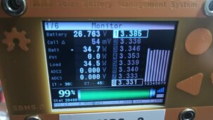
I think set number 7 was down to 2.4 volts or so (in the 2P8S build)....wish the picture would have came out better but,,,,the android cellular camera is the el cheapo version...

thanks Koobs for the reply....?
 
EVE LF280K LiFePO4 6000 cycle rated update:

yesterday, February 1st 2024 the SBMS0 and the 4P8S battery was fully charged and thereWhatsApp Image 2024-02-01 at 5.46.05 PM.jpeg is a small cell deviation (delta) with it looks like cell group #1 being the highest voltage...
I have it measuring groups of 4 cells as they are paralleled 1st before the series connections.... 4P8S configuration 32 cells of the EVE LF280K with welded-on screw holes...
This is just a small update as it has been functioning daily since 2020 or 2021 I forget...the exact date
 
At that cell voltage at just over an amp of load current it indicates cells are not balanced in SoC.

Four 280 AH cells directly connected in parallel are going to need a balancer with a lot of current dumping capability to make much of an impact in a reasonable amount of balancing time.

You can also have cell matching issues. Better to have four separate BMS's and parallel four battery packs.
 
Last edited:
It is almost impossible for a DIY'er to get truly matched cells. Matching is much more than just cells with same AH capacity.

When directly parallelling cells it is very important for cell overpotential voltage slump versus load current to match. Just a small amount of overpotential mismatch will cause parallelled cells to significantly not share total load current equally.
 
Right now it has a cell delta of 4-6 mV on February 2nd,2024 so the passive balancing on the 4P8S is working fine....on the 32 cell 4P8S EVE LF280k using the 280 Ah cells.
about 74 degrees in the off-grid solar power shed this morning ...
the two Ridens buck battery chargers add a fair amount of heat and I have one 100-watt light running all the time to add some heat in the wintertime...37 degrees Fahrenheit outside this morning...
I shut the Ridens battery chargers down overnight also...
 
At that cell voltage at just over an amp of load current it indicates cells are not balanced in SoC.

Four 280 AH cells directly connected in parallel are going to need a balancer with a lot of current dumping capability to make much of an impact in a reasonable amount of balancing time.

You can also have cell matching issues. Better to have four separate BMS's and parallel four battery packs.
I have a couple of other chargers that put out 20 to 40 amps each but I was just getting going as I am reinforcing the new shelf to support all that weight of 64 cells....likely over 800 pounds ,,, looking for a hydraulic jack or a screw jack to adjust the shelf a bit today...

I am sure they are not perfectly balanced....
but if they are at 4-6 mV delta from high cell to low cell this morning they are pretty darn close to being balanced and that does not seem too far out of control for a 2-plus-year-old battery build....
could be I need to check the connections....as the torque was not an exact science when I was assembling it...
moving a lot of stuff to make more room in the off-grid solar power shed.. slow but sure...
as lots of other duties on the off-grid farm....
Lambing season is in full tilt also...

(((((I am just charging in pairs of paralleled cells at the moment with one Riden buck battery charger on each pair of cells...(my new project)
when I get 8 or 16 top balanced I will likely start more assembly into 24-volt batteries...... I am working on a new set of 64 cells 280Ah version 3 cells for a larger ESS....))))

the low load was at dusk and I was shutting everything down for the night... think it was just the 3200-watt inverter and a couple of lights running at that point in the photo. yesterday... (maybe 150 watt load)....
 
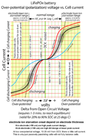
Overpotential voltage will prevent passive parallel balancing from achieving better then about 10 millivolts of cell open circuit voltage difference. That can translate to about 5% SoC difference which is massive.

An LFP cell will have 10-25 millivolts of overpotential for very low amount of cell current. If you separate cells and allow them to sit for a while the difference will become apparent.

LFP Over-potential Chart.png
 
Last edited:
Overpotential voltage will prevent passive parallel balancing from achieving better then about 10 millivolts of cell open circuit voltage difference. That can translate to about 5% SoC difference which is massive.

An LFP cell will have 10-25 millivolts of overpotential for very low amount of cell current. If you separate cells and allow them to sit for a while the difference will become apparent.

View attachment 192833
that is very interesting;
I will have to study up more; I believe the Electrodacus SBMS0 stops charging at something like 95 percent SoC or something and stops discharge before fully discharged if a compatible inverter is being used....
I ran into the over-discharge problem one time (my inverter was not being controlled by the SBMS0) and both charge and discharge was disabled until I charged the battery manually from a different battery....
thanks for the reply and information....

can you point me to the reference materials??? who wrote this article and published the information?
evidently, LiFePO4 has been around a long time but the prices have decreased and is somewhat more doable for DIY solar PV people....
I had used lead acid batteries before but they were a lot of maintenance...

Still learning... I am not an engineer or a electrician🤔

when they are setting overnight >>>> do the parallel cells tend to balance ???? the above says 3-4 minutes to reach equilibrium....
i do see where it says passive balancing will not fully balance the cells

so it seems to Imply an active balancer is required which could be set up periodically if absolutely necessary???
 
if they are charged to 99 percent SOC then the 100 mV - 200 mv was likely never reached in the above starvation diagram....
am I missing something???? or misinterpreting something???
if the SBMS0 turns off the charging to prevent over-voltage....
I do not do heavy rates of discharge an 1120 amp battery to do a .5C rate of discharge would have to pull 280 amps for over 2 hours continuously .... or would .5C discharge actually be 560 amps which I never do on any discharge... at the laboratory 25 degrees celsius???

am still mis-interpreting something... .5C charge rate on an 1150 amp battery would also be 560 amps which again I do not do this to these DIY LF280k cells...

you got me going around in circles in my head >>> trying to interpret a graph with no voltages actually shown????🤔

again I am not an electrical engineer or an electrician so point me in the right direction....

LiFePO4 full charge is 3.65 volts per cell... and you do not want to go over that as that will damage the cells is my understanding...
3650mV minus 200 millivolts is 3450mV
I believe the Electrodacus SBMS0 stops charging when any cell reaches 3.55 volts and when it settles back down it is rarely if ever above 3.40 volts
 
A LiFePO4 battery's voltage varies depending on its state of charge. The voltage rises as the battery charges and falls as it discharges. The relationship between voltage and state of charge is non-linear, meaning that a small change in SOC can cause a significant change in voltage.

How do I know when my LiFePO4 battery is fully charged?


So how can you know the state of charge of a LiFePO4 battery? The only accurate way is with an AH meter. An amp hour meter measures the amount of amp hours used. So if you have a 100AH battery and the meter shows you have 70 amp hours left it's a no brainer, you know your battery is seventy percent charged.Dec 16, 2021

I found the above that on a google search
 
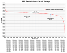
An LFP cell is fully charged when its open circuit rested voltage is 3.43 vdc. There is a couple mV variance to this number based on matching of graphite and LFP electrodes capacities.

Any open circuit voltage between 3.43v and 3.65v is due to surface capacitance charge which has very little contribution to capacity of cell. It will bleed off the capacitance charge on its own within several hours to a couple of days, or you can quickly bleed it off with a short duration load on cell for about a minute or two.
LFP typ Open Circuit Voltage vs SoC.png
 
Last edited:
It is almost impossible for a DIY'er to get truly matched cells. Matching is much more than just cells with same AH capacity.

When directly parallelling cells it is very important for cell overpotential voltage slump versus load current to match. Just a small amount of overpotential mismatch will cause parallelled cells to significantly not share total load current equally.
This makes sense to me, however for low C rate applications (solar storage), does it matter so much if a one cells has a 0.1C load and another paralleled cell 0.09? All the cells are way below their max continuous discharge rate.

And presumably, as long as the battery pack is charged to a high SOC on a regular basis ( i.e. up past the 90% point on the over-potential chart) the cells doing the heavy lifting on discharge will charge first and then begin flowing current to their paralleled neighbours as they get into the "knees".

I would really like to understand this issue better, as it comes up a lot on the forum. I have a 4P4S (400ah) battery in my basement which has been performing perfectly for some time now (i.e. max 15mv deviation even at top of the charge curve (3.55 volts).
 
last night February 2nd, 2024 >>> after dark the Electrodacus SBMS0 #3 was showing a 6 mV delta on the 32-cell build 4P8S using the eve lf280k cells.
the inverter was on and powering a very small load,, basically lights at night as the inverter is on 24/7..
each set of 4 paralleled cells only showed a 6 mV delta from high to low voltage and I think it said 96 percent SOC .... that seems pretty good to me...
these are only being charged with Solar panel PV using Electrodacus DSSR20 as the charger. and the Electrodacus SBMS0 as the BMS
 
the cells are not being charged to 3.65 volts by the solar PV they are being charged with all the Electrodacus DSSR20 will give them and are being passively balanced by the SBMS0....

the 99 percent SOC is not 3.65 for all cells in the SBMS0 with dssr20 as the charger...
3.65 x 8 equals 29.2 volts and the battery never is charged and operating to that high level.....

I will have to get into the electrodacus details more but it is not continually being overcharged by the solar PV....
but I do want to understand it better....
The battery in use is never at 3.65 volts usually closer to 3.35 or less per cell
27.2 is closer to normal operating voltage of the 24volt builds or slightly less...
27.2 divide by 8 equals 3.4 volts per cell or group of cells in parallel...

I do not monitor that number continuously the SBMS0 does that....
this is an off-grid solar PV stationary system that has been functioning for 2-3 years without too many issues...
the biggest issue is not properly controlling the inverter discharge as my inverter is not yet set up to be fully compatible with the electrodacus SBMS0...

thanks for the replies....
it was cloudy all day yesterday but the sun is coming (groundhog predicticted it)😎
 
STC means Standard Test Conditions and that means 1000W/m^2 of solar irradiation and panel temperature of +25C
For panels to be at +25C ambient will need to be way below freezing.
The 10.82A is the max power point current when max power point voltage is at 34.2V in STC so the panel rating 10.82A * 34.2V = 370W
Normal conditions the panel temperature will be quite a bit higher than +25C unless is a cold winter day around -10C.
So say with panel temperature around +65C the max power point voltage will decrease at 0.29% per degree Celsius and with 65C - 25C = 40C delta * 0.29 = 11.6% decrease in max power point voltage
34.2V * 0.116 = 3.967V
Thus max power point voltage at +65C panel temperature will be 30.23V
Now the battery voltage is around 27V most of the time so there are still sufficient margins to have some voltage drop on the wires say around 1.5V the voltage at the PV panel terminals will be 27V + 1.5V = 28.5V slightly below 30.23V max power point
Max power point current is also affected slightly by temperature but in the other direction so 40C * 0.05 = 2% thus 10.82A * 0.02 = 0.216A so max power point current 11.036A
Since voltage at panels will be lower than max poser point voltage 28.5V in those conditions the current will also be closer to short circuit current 11.42A + 0.216A = 11.636A

Max power point for +65C panel temperature at noon with no shadow on panel 30.23V * 11.036A = 333.6W at panel when including drop on wires and say a 95% efficient MPPT you can get (30.23 - 1.5) * 11.036A = 317W
Max power with DSSR50 at +65C 28.5 * 11.6A = 330.6W at panel and at battery 27V * 11.6A = 313.2W
11.6A * 4 panels = 46.4A but that is for solar at 1000W/m^2 and many times solar can be at 1100W/m^2 and current is directly proportional with the amount of solar irradiation and thus in that condition it can be 51A
For a few seconds you can have even higher peak currents due to edge of clouds effect (when clouds reflect more light on the panels) and snow can do similar things depending on panels angle to sun then you can get even 13 or 14A from each of this panels for typically a few seconds but that is fine as DSSR50 can handle 60A for short periods with no problem so 4 of this panels will work perfectly with DSSR50.

soon I will be using the new Electrodacus DSSR50 in conjunction with the Electrodacus SBMS0 with some 72 cell panels.
 
resting voltage is when the battery is not being charged...
my batteries are not being charged and kept above 3.43 volts per cell (maintained above 3.43 volts)... as far as I can tell

at night when there is not any solar PV charging of the ESS battery build of LiFePO4 DIY batteries it would kind of be like the resting voltage....
except the inverter is on and connected and small loads are running at night 24/7...

the 4P8S 32-cell using EVE LF280k prismatic cells has 1120 Amps (280 x4 = 1120 amp capability) but I do not pull 1120 amps from it... at any time
 
batteries in parallel tend to self-equalize and act as one battery is my understanding...

2 cells in parallel act as one single cell...
4 cells in parallel act as one single cell...
8 cells in parallel act as one single cell.....
as you parallel more cells the amperage goes up

2 x 280 = 560 Amps
4 x 280 = 1120 Amps
8 x 280 = 2240 Amps

it has been repeated repetitively that no two cells are exactly alike..... and essentially all cells sold are a so-called grade b cell ... some better than others...
grade A AUTOMOTIVE CELLS cost more and have documentation, but it has also been shown there is not much functional difference between them in a solar storage system with PV panels so why pay twice the money for not much return on that investment..

eventually, there may be a better storage method than LiFePO4...

just as every 12-volt battery has cells in parallel and cells in series to get 12 volts or 24 volts or what have you....
those internal cells are not always running in perfect unison and some batteries will function better than others depending on how they are being maintained....

the Electrodacus SBMS0 is the maintainer in part on my off-grid solar PV system...
I am the maintainer in part by trying to moderate the ambient temperatures of the LiFePO4 DIY builds,,,,
ie >>> an insulated outside solar power shed for the batteries.... I do not want them (the LiFePO4 cells) in my house...
for safety reasons as the young and unaware people could poke their fingers and noses in the wrong places🤔
 
If you are continuously maintaining LPF cell voltage above 3.43v you are overcharging it and will degrade the cell.
 
Back
Top