efficientPV
Solar Addict
- Joined
- Sep 24, 2019
- Messages
- 1,341
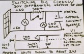
I've been diverting excess PV power to heat water at my camp for years. It is the only source of hot water as I got rid of my propane heater. A simple method is used to determine when there is excess power. At the power point voltage, the maximum power is obtained from the panels. Use less power and the voltage will rise up to the open circuit voltage depending on the current. Light intensity only changes the panels current, not the power point voltage. This circuit diverts enough current to drop the panels voltage back to the power point. It can be used in parallel with PWM and MPPT controllers. No battery is needed and it can operate in stand alone mode.
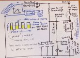
The principal of operation is energy is stored in a capacitor bank and is PWMed to a heating element. Here is a simple example. Think of a 10A heating element which is ideally matched to the solar in best conditions. In less than ideal sun that panel can produce 5A. For 50% of the time the panels 5A charges the capacitor bank when the heating element is turned off. In the next 50% the heating element turns on and receives a full 10A, 5A from the solar panel and 5A from the capacitor bank. The panel always sees the same ideal voltage so it operates at maximum power. The duty cycle is changed by sensing thevoltage on the capacitor bank and is kept within a fraction of a volt. Updates are 120 times a second.
Here is a video of a commercial product AC7931 that does this. I have not personally used it. It does miss design targets because it requires an external isolated power supply, has to use an internal fan, and capacitor bank may not be large enough for long life.
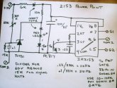
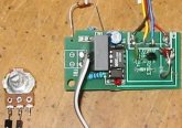
There are many circuits that can accomplish this from discrete to micro and I've built most of them. This is the heater control I use at home. It is an unconventional use based on a IR2153 half bridge driver chip which provides many of the functions needed at very low current. It is highly stable with built in voltage regulator, FET driver, oscillator and under voltage protection to prevent FET damage. Pictured in case is a low cost board from China which was modified. I can no longer recommend these because which board you get now totally random regardless of what the listing says. Some have the correct 8 pin chip and some the 16 pin SG3525 chip. Both can be made into controllers. However, they now come with 55V FET which makes them only suitable for 36V arrays max. Poor trace layout also makes them unsuitable for more than 60V. The very small number of components make it suitable for a perf board construction and I recommend using four 110N15 which are 110A 150V FET.
Reasons to divert power from panels instead of battery
1. Lower current and lower resistance losses with higher voltage
2. Smaller charge controller
3. Smaller battery bank
4. No double or tripple conversion loss from charge controller, battery, inverter
5. Battery left as fully charged as possible
6. Does not interfere with charge cycles
7. Captures energy when charge controller is not transfering maximum
power to battery during charge stages
8. Inability to actually know charge state of battery
9. Can capture even small amounts of extra power
10.Often uses standard heater elements instead of battery types
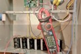
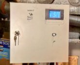
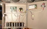
An interesting feature of this circuit is mechanical AC thermostats can be used in switching primary DC supply without arcing when the array is less than 100V. A capacitor bank of about 6,000uF is required made of multiple capacitors to handle the high surge currents. The front panel consists of a power meter and a pot to set the voltage. A switch also allows direct connect to the heater elements for performance comparison. Here are some typical values. Due to low tilt, maximum panel power is about 395W into 7.5 ohms. 44W may not seem like much, but that is what is needed to replace lost heat. The blue wire out of the power meter is a modification to provide external power. Low power levels of direct connect often do not provide enough voltage to self power the meter. Also shown is a breadboard build.
POWER POINT DIRECT
44W 5W
65W 9W
117W 47W
118W 52W
205W 103W
265W 195W
302W 226W
The principal of operation is energy is stored in a capacitor bank and is PWMed to a heating element. Here is a simple example. Think of a 10A heating element which is ideally matched to the solar in best conditions. In less than ideal sun that panel can produce 5A. For 50% of the time the panels 5A charges the capacitor bank when the heating element is turned off. In the next 50% the heating element turns on and receives a full 10A, 5A from the solar panel and 5A from the capacitor bank. The panel always sees the same ideal voltage so it operates at maximum power. The duty cycle is changed by sensing thevoltage on the capacitor bank and is kept within a fraction of a volt. Updates are 120 times a second.
Here is a video of a commercial product AC7931 that does this. I have not personally used it. It does miss design targets because it requires an external isolated power supply, has to use an internal fan, and capacitor bank may not be large enough for long life.
There are many circuits that can accomplish this from discrete to micro and I've built most of them. This is the heater control I use at home. It is an unconventional use based on a IR2153 half bridge driver chip which provides many of the functions needed at very low current. It is highly stable with built in voltage regulator, FET driver, oscillator and under voltage protection to prevent FET damage. Pictured in case is a low cost board from China which was modified. I can no longer recommend these because which board you get now totally random regardless of what the listing says. Some have the correct 8 pin chip and some the 16 pin SG3525 chip. Both can be made into controllers. However, they now come with 55V FET which makes them only suitable for 36V arrays max. Poor trace layout also makes them unsuitable for more than 60V. The very small number of components make it suitable for a perf board construction and I recommend using four 110N15 which are 110A 150V FET.
Reasons to divert power from panels instead of battery
1. Lower current and lower resistance losses with higher voltage
2. Smaller charge controller
3. Smaller battery bank
4. No double or tripple conversion loss from charge controller, battery, inverter
5. Battery left as fully charged as possible
6. Does not interfere with charge cycles
7. Captures energy when charge controller is not transfering maximum
power to battery during charge stages
8. Inability to actually know charge state of battery
9. Can capture even small amounts of extra power
10.Often uses standard heater elements instead of battery types
An interesting feature of this circuit is mechanical AC thermostats can be used in switching primary DC supply without arcing when the array is less than 100V. A capacitor bank of about 6,000uF is required made of multiple capacitors to handle the high surge currents. The front panel consists of a power meter and a pot to set the voltage. A switch also allows direct connect to the heater elements for performance comparison. Here are some typical values. Due to low tilt, maximum panel power is about 395W into 7.5 ohms. 44W may not seem like much, but that is what is needed to replace lost heat. The blue wire out of the power meter is a modification to provide external power. Low power levels of direct connect often do not provide enough voltage to self power the meter. Also shown is a breadboard build.
POWER POINT DIRECT
44W 5W
65W 9W
117W 47W
118W 52W
205W 103W
265W 195W
302W 226W
")