diy solar

diy solar

Experiences charging LFP from alternator WITHOUT a DC-DC charger

There is a high chance that a failing alternator in a modern vehicle will take some/all of the vehicle computer modules with it.

Do the sums and calculate the resistance of the path between the alternator and the battery, factor in the battery internal resistance and the alternator output resistance. This is limiting the current together with the alternator volts drop as it approaches full power output.

Mike
Yup, this is exactly what I have seen. The 9mR resistance between the van battery and house battery keeps the charge rate at 80-100 amps and the increased 20mR setup is keeping the charge rate at 40-50 amps (so far). In both cases the 220 amp alternator has not dropped it's voltage. I do see a few tenths of a volt drop at the van battery but this is likely due to resistance in the current path from the alternator.
 
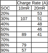
These are the charging rates I have seen with an alternator-battery direct hookup to a 240Ah LiFePO4 battery. In the first case the cables/fuses/connections/shunt add up to around 10mR and in the second case the addition of a resistor bumps it up to around 20mR. The voltage from the alternator sits at around 14.37 at the van battery (prior to the wiring that leads to the 'house' battery).

In my case I am pretty happy with the direct connection. However, I use so little power in summer that the lower rates with the resistor are still more than enough. For folks with lower output alternators, or doubts about the alternator thermal regulation, it seems like the use of a resistor is pretty effective. Although you have to accept lower charge rates at a high state-of-charge it stays surprisingly high up until 90%!


Screenshot from 2021-03-21 16-02-36.png
 
These are the charging rates I have seen with an alternator-battery direct hookup to a 240Ah LiFePO4 battery. In the first case the cables/fuses/connections/shunt add up to around 10mR and in the second case the addition of a resistor bumps it up to around 20mR. The voltage from the alternator sits at around 14.37 at the van battery (prior to the wiring that leads to the 'house' battery).

In my case I am pretty happy with the direct connection. However, I use so little power in summer that the lower rates with the resistor are still more than enough. For folks with lower output alternators, or doubts about the alternator thermal regulation, it seems like the use of a resistor is pretty effective. Although you have to accept lower charge rates at a high state-of-charge it stays surprisingly high up until 90%!


View attachment 41913
Bzzzt, good info, I appreciate it,

I have giant alternators in both my Diesel and Ferd 3.5 Eco,
100 Amps or 50 amps, wow, 2 awg cable huh?

My Ferd 3.5 Eco is wired for 60A behind my driver's seat.

So adding a shunt on the negative wire will be enough to raise the resistance of the system to 20mR?
 
Bzzzt, good info, I appreciate it,

I have giant alternators in both my Diesel and Ferd 3.5 Eco,
100 Amps or 50 amps, wow, 2 awg cable huh?

My Ferd 3.5 Eco is wired for 60A behind my driver's seat.

So adding a shunt on the negative wire will be enough to raise the resistance of the system to 20mR?I
If you have 'giant alternators' maybe you can comfortably skip adding extra resistance? However, If your battery pack is massive then you might end up hoping the alternators can protect themselves.

The current path to my batteries includes around 10 feet of 1 gauge, a dab of dual 6 gauge, a switch, two mega fuses, two 5/16" steel bolts, and a 0.00075 ohm shunt. Altogether that is just a hair under 0.009 ohms without the added resistor. Clearly everyone will have a different value for their wiring. What I can say is that adding a 10 milli-ohm resistor will make a sizable dent in the current. That resistor has to dissipate a fair bit of heat though - be sure to mount it up on an appropriate heat sink with ample airflow or it won't last long.

I used the following (https://www.digikey.ca/en/products/detail/ohmite/TGHGCR0010FE/1817153). The terminals on this are M4 (!!!) which are NOT reassuring! I had to use some short single 6 gauge leads to tie it into the system and even with that small wire the resistor is dwarfed. I'd love to see if anyone has found a 10 mR resistor with a larger case and beefier leads!
 
These are the charging rates I have seen with an alternator-battery direct hookup to a 240Ah LiFePO4 battery. In the first case the cables/fuses/connections/shunt add up to around 10mR and in the second case the addition of a resistor bumps it up to around 20mR. The voltage from the alternator sits at around 14.37 at the van battery (prior to the wiring that leads to the 'house' battery).

In my case I am pretty happy with the direct connection. However, I use so little power in summer that the lower rates with the resistor are still more than enough. For folks with lower output alternators, or doubts about the alternator thermal regulation, it seems like the use of a resistor is pretty effective. Although you have to accept lower charge rates at a high state-of-charge it stays surprisingly high up until 90%!


View attachment 41913
I=V/R so we can calculate the current. i'll assume the battery is at 13.3v and it has 0.25mR internal resistance:
(14.37-13.3)/(.01+.00025)=104 and (14.37-13.3)/(.02+.00025)=53.
So your numbers are right as expected based on the measured system resistance.

Worst case would be down in the low voltage shoulder (most try to avoid such a deep discharge), like 12v: (14.37-12)/(.01+.00025)=231! At least at idle that would overwhelm the alternator and pull your system down from 14.37V, but the battery won't stay that low very long either.

Your system resistance sounds somewhat high looking at wire charts, but adding in the charge disable relay, two fuses, two cutoff switches, the BMS, and the various connections I Imagine I'll be similar.
 
And let me just say I'm just throwing numbers out there... I don't know what the internal resistance should be (.25mR I read in a post someone measured, but it seems it should be roughly .1/Ah rating of the battery?) nor what the system resistance should be. But if those numbers are inline with expectations, it seems like this isn't a huge issue unless you discharge those batteries super low.
 
I love back of the envelope calculations, especially when they work!
And let me just say I'm just throwing numbers out there... I don't know what the internal resistance should be (.25mR I read in a post someone measured, but it seems it should be roughly .1/Ah rating of the battery?) nor what the system resistance should be. But if those numbers are inline with expectations, it seems like this isn't a huge issue unless you discharge those batteries super low.
 
what about the voltage drop, won't it limit V to the battery even more?
not sure how you'll get a full charge i.e. whatever you deem full is 14.4V, 14.2V
 
what about the voltage drop, won't it limit V to the battery even more?
not sure how you'll get a full charge i.e. whatever you deem full is 14.4V, 14.2V
Fortunately, the voltage drop is proportional to the amps flowing. As the batteries increase in voltage the current drops, resulting in a lower voltage drop through the system. I have not had any issue hitting my high voltage cutoff at the end of charge.
 
Fortunately, the voltage drop is proportional to the amps flowing. As the batteries increase in voltage the current drops, resulting in a lower voltage drop through the system. I have not had any issue hitting my high voltage cutoff at the end of charge.
Yeah, one of the biggest mistake inpatient people do when charging is raising the voltage to increase the amps, but they forget the drop will not be the same as the current decreases.
Hence the need for sense cables or a better PS :)
 
Thank you for sharing this to get some real understanding of what amp rates to expect in a real direct charging set up. So If we wanted to be able to to charge at let's say 150A and we have an alternator that can handle it the real problem (after lowering the resistance conecting the house battery) would be that it would put too many amps at lower SOC of the battery .
I have seen utubes of people raising the alternator voltage by increasing the reference voltage at the alternator with a resistor or a diode....I wonder how dificult would be to get an arduino microcontroller to raise the voltage instead at the reference voltage line of the alternator reliably when the SOC gets low to lower the alternator voltage and lower the current. That would be a neat set up.
I don't know where in a modern vehicle the alternator is controlled. You are right though, if you could trick the controller into seeing a different voltage you could take control of the alternator output voltage. The logical step to full alternator control seems to have been taken by Wakespeed (http://wakespeed.com/products.html).
 
I've looked into alternator hacking (likely via arduino - enable a resistor in parallel to the regulator to up the voltage, add resistance in series to lower), but that seems potentially problematic on a modern vehicle and I'm not convinced it's necessary for my application. I'd maybe consider it if I went dual alternator, but I'm pretty sure I'd end up with a wakespeed regulator instead.
 
I just stumbled onto this thread and want to throw out my dilemma. I am currently building an overlanding rig on a Dodge Cummins with dual 220 amp heavy duty alternators. I bought a truck camper without an electrical system so I can spec it myself. I'd like to build my own battery from Fortune cells and control charging with the BMS. I should be able to get 700ah at 12v into the battery box in the camper. I'll install as much solar as I can fit but I want to get the max charge from the alternators when under way since I'll be running a 12v air conditioner often when parked and I know solar won't keep up. Problem is, I can't add an external regulator to the alternators as they are controlled by the truck's ECU. I don't really want to buy another alternator since I have 2 brand new heavy duty units. The charging voltage of the alternators is (supposedly) set at a solid 14.4v. Do I take a chance and use the BMS to open/close a 500a relay (off of the starting battery) so I can control the charge parameters based on the cell's actual voltage/current? Do I use the BMS to switch on/off something like the Victron Buck Boost 100a where I'd have much less current available? Is there a better option? Been looking at a ton of threads for a solution and getting a lot of conflicting answers. Mercy on this newbie!
 
I just stumbled onto this thread and want to throw out my dilemma. I am currently building an overlanding rig on a Dodge Cummins with dual 220 amp heavy duty alternators. I bought a truck camper without an electrical system so I can spec it myself. I'd like to build my own battery from Fortune cells and control charging with the BMS. I should be able to get 700ah at 12v into the battery box in the camper. I'll install as much solar as I can fit but I want to get the max charge from the alternators when under way since I'll be running a 12v air conditioner often when parked and I know solar won't keep up. Problem is, I can't add an external regulator to the alternators as they are controlled by the truck's ECU. I don't really want to buy another alternator since I have 2 brand new heavy duty units. The charging voltage of the alternators is (supposedly) set at a solid 14.4v. Do I take a chance and use the BMS to open/close a 500a relay (off of the starting battery) so I can control the charge parameters based on the cell's actual voltage/current? Do I use the BMS to switch on/off something like the Victron Buck Boost 100a where I'd have much less current available? Is there a better option? Been looking at a ton of threads for a solution and getting a lot of conflicting answers. Mercy on this newbie!
That is a good sized battery! Are these alternators hooked up together for 440 amps?!?

I'd lean towards the bms controlled relay between the starter battery and the lithiums. That said, I don't know what start-stop parameters your bms will allow. If it has a cell based high voltage cutoff then I don't see this being an issue. Would this relay also cut out the connection when the engine stops?

The big unknown is whether your alternators protect themselves from thermal overload. The resistance through your wiring should limit the current to the battery to a large extent but in extreme cases (very low state-of-charge) the batteries might be capable of pulling 100% of your alternators output. You want to know that while idling at high temperatures your alternators aren't cooking.

Likely the biggest issue is your own willingness to accept risk! Plenty of companies will happily take your money in exchange for piece of mind.
 
440A is quite a lot. If you look up at the math I did you'll need super low resistance between the starter battery/alternator and the lithium batteries to get anywhere near that in the normal range of ~13v. Lets just say you want 300amps, Thats a 1.4v voltage drop so R=V/I 1.4/300 = .00467ohm or half of what Bzzzt measured and it will fall off as the voltage rises.

At your battery size and loads you may want to consider a 24v system anyways and there direct connection isn't an option unless you swap one of those alternators. I have no experience with them, but one of these baddies may be an option for you: https://www.daygreen.com/collection...00w-dc-dc-step-up-converter-voltage-regulator. That should be roughly constant power for you until near the end of the charge and you won't have to worry about the resistance quite so much to get that full power.

As for cooling, I'm thinking of attempting to chill my onboard water with the vehicle AC as I drive and use that to chill the cabin while we sleep (similarly heat the water when we are in the cold and want heat). I purchased 16 280Ah cells thinking I'd run AC on my overlanding rig also, but I'm now going to try running half the batteries and skip that.
 
Last edited:
I'm def gonna be using welding cable for my connections. I'd love to change to a 24v system but already own the dual 220a 12v setup so I'll try to work with it. I've looked at the mini splits but want to run the AC off of battery power only. The Cruise N Comfort 12v AC units aren't too spendy amp-wise. Have you seen this rig? https://www.truckcampermagazine.com/off-road/extreme-rigs/the-cost-no-object-expedition-camper/ I want the budget version of that! He said he's charging his batteries at 68 amps in the article from the same alternator setup. Seems like I can get more so I can top off on a shorter drive. I'm still trying to find the best BMS/relay for the job and I am open to suggestions. I could use the Sterling 12v 210a alternator to battery charger https://www.sterling-power-usa.com/sterlingpowerusa12volt-210ampalternator-to-batterycharger.aspx) with a BMS controlled relay to regulate the voltage and current and overcome the drop and have 210a to play with. The Sterling doesn't have a CANBUS interface or any way to control or program it so seems kinda dumb. The Victron Buck Boost 100a can be programmed and BMS controlled and would overcome the drop as well. That's the dilemma! Thanks for the input!
 
I'm don't remember why I eliminated that Sterling system from consideration (or maybe I didn't see it?), that is worth a second look though, could solve a few issues. I ordered an Electrodacus SBMS0 for my BMS. It doesn't have a built-in FET limiting the current capacity (you could add something like this if you wanted) and it has flexible charge/discharge enable outputs.
 
Sterling units do not perform well in high ambient temperatures, you have been warned.

If possible you may consider just having the 2nd alternator removed from the ECM/ECU programming, and install an external regulator. Then dedicate that alternator purely to aux bank charging.

In that case you could also have the alternator rewound for 120A at 24V. Then switch your camper battery setup to 24V. A 700Ah at 12V bank is going to be more difficult for various reasons. A 350AH @ 24V bank has advantages.


I would be very surprised if those alternators couldn't handle whatever there max output is at idle without overheating. I think much of the hand wringing about protecting the alternators is unnecessary. I can count on one hand the number of alternator meltdowns in newer vehicles I have seen. Even with farmers running winches, charging battery banks etc.

Regardless you can test the alternator pretty easily. Get a 2-3kw 12V inverter wired up, and then put an adjustable load on it. A couple cheap space heaters from your local mega-mart will work fine. Start at 1kw and add load until the alternator voltage drops below ~13.5V. Hold that for 10 minutes and use an infrared thermometer to watch the alternator case temperature. If it stays under about 220F in modest ambient temps (at idle) then you have nothing to worry about.
 
Last edited:
Good idea, minimize the resistance first and see how it goes. If that's not enough the next logical step is put a wakefield or whatever external regulator on the second alternator and go dedicated (less peak, but higher sustained output as it can charge at a higher voltage)
 
What are the advantages of that battery bank being 24v other than thinner cable from alternator?
Double the power for a particular current so you can use smaller gauge wires, lower rated electronics, less heat loss. Cost wise I think it works out pretty similar on my vehicle (as it's not very large and I'm not doing much solar) but the edge went to 12v when I considered the much wider general availability of 12V accessories and replacement parts vs 24v. If you are considering international overlanding that could be a deciding factor for you as well.
 
Back
Top