diy solar

diy solar

Externally controlling a non-controllable charge controller

Sverige

A Brit in Sweden
Joined
Oct 8, 2020
Messages
740
Location
59.5N, 15.5E
It seems it’s mostly the more expensive charge controllers which make provision for external enable / disable control via a closing contact. What all of the cheaper charge controllers seem to have in common though is over temperature protection which shuts off charging when the internal temp reaches something like 75-85C.

So I have an idea - given that thermistor resistance has an inverse relationship to temperature - ie. resistance drops as temp rises, how about switching via a closing contact a low value resistor in parallel with the thermistor? In other words, open up the charge controller, solder a pair of wires either side of the thermistor and between those two wires connect your controlling device (which opens or closes a dry contact) and a low (1kOhm?) resistor.

Control signal is open contact, charging runs as normal. Control signal goes closed contact and SCC sees a below 1kOhm resistance from the onboard thermistor and perceives this as over temperature and shuts off charging.

I really can’t be the only one to have thought of this, so I wonder who’s tried it and how did it work out? My controlling device will be an electrodacus BMS and with this proposed approach I’ll avoid the cost (and inefficiency) of solid state relays inline with the PV input.
 
Usually people use contactors (relays) or solid state relay for this.
Last one isn't the best choice as it's built for many contacts for short periods, many periods.
Contactors are build to make connection and keep it for longer periods of time.

Both will use some power, SSR being more energy efficient, also more prone to failure.

Thermal safety switch. Isn't something to play with.

You probably could attach something that works as trigger, but you loose the protection!

It would be easier it they have on/off switch...
Now the most used way is to switch the solar or battery cable.

For me, I have hybrid inverter, mppt build in. The power button does control the inverter, but not MPPT.
That always works when the sun shines.
So I have 50A (way overrated) contactor for my 20A solar connection, controlled by my BMS.
Thanks - I’m aware of the normal approach, as you say it has drawbacks. I’m proposing this as an alternative.

Why do you say thermal protection isn't to be played with? I can’t see how what I’m proposing would prevent a regular over temp event being correctly sensed.
 
It seems it’s mostly the more expensive charge controllers which make provision for external enable / disable control via a closing contact. What all of the cheaper charge controllers seem to have in common though is over temperature protection which shuts off charging when the internal temp reaches something like 75-85C.

So I have an idea - given that thermistor resistance has an inverse relationship to temperature - ie. resistance drops as temp rises, how about switching via a closing contact a low value resistor in parallel with the thermistor? In other words, open up the charge controller, solder a pair of wires either side of the thermistor and between those two wires connect your controlling device (which opens or closes a dry contact) and a low (1kOhm?) resistor.

Control signal is open contact, charging runs as normal. Control signal goes closed contact and SCC sees a below 1kOhm resistance from the onboard thermistor and perceives this as over temperature and shuts off charging.

I really can’t be the only one to have thought of this, so I wonder who’s tried it and how did it work out? My controlling device will be an electrodacus BMS and with this proposed approach I’ll avoid the cost (and inefficiency) of solid state relays inline with the PV input.
A SSR uses only milliwatts and a good high amperage contactor (like a gigavac) only uses 1.5-3 watts to hold, what you're proposing would actually eat up a lot more power heating up your thermistor than either of those solutions. Furthermore you're injecting extra heat and electric fields into a system that wasnt designed to account for it.

The reason it's not done is there are much better ways to go about what you want to accomplish.
I don't think he is heating anything up .... just tricking the temperature input.

I personally like the philosophy of avoiding switching the battery side of things with a BMS .... If I were buying a new charger, I would try to get one that had a power switch or remote control capabilities .... but if I needed to control an existing device, I would consider this strategy .... and test, test, test.
You're right, I didnt read it correctly. My bad. He's tricking the SCCs temperature sensing circuit.

However thermistors come in two flavors NTC and PTC, NTC the resistance goes down with temp, PTC the resistance goes up with temp.

No telling what type a SCC is using. If the charge controller is using a PTC it wouldnt work as it would think that a closed signal is it just got extremely cold so it continues to operate. Also, how is the closed signal being generated? By a relay/SSR?
But now we're back to having to hold a signal open or closed and the power for that is still being drawn somewhere and a SSR is still a better and less complicated means to accomplish the goal. The power to trigger a 100A SSR is about the same as triggering a 10A or a 1A SSR.
 
But now we're back to having to hold a signal open or closed and the power for that is still being drawn somewhere and a SSR is still a better and less complicated means to accomplish the goal. The power to trigger a 100A SSR is about the same as triggering a 10A or a 1A SSR.
Yeah, but if you are like me and trying to avoid switching that 100A circuit ..... most of the charge controllers say don't disconnect the battery while there is input power, but everyone does it anyway ....plus, the SSR to control 1A is going to be a LOT less expensive than the 100 A one and will be a lot less prone to failure from having to pass that high current all the time. The heat .... which is also power loss .... from a high amp SSR can be significant also.
 
I'm no electronic wizard.
I have handled a few MPPT, and saw their internals.
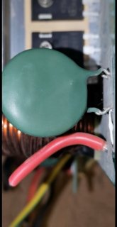
All of them had thermal safety like this compinent:
2021-3-23 10-8-17_copy_540x1045.jpg

I don't know it's exact name, but do know how it works, stops contact when too hot, and when it cools down enough, start the contact again.

Not a standard thermistor that provides information to a more software approach of controlling.
The thermistor itself doesn't do anything..
And indeed, if the mppt would have that part, you know it's values, you probably can use a small resistor to mimic the value that would sense like "90 degrees".
Best way to test is measure the resistance under different temperatures.
If it's used.

Most MPPT, including my PowMr, have this "hardware" approach.
No software failure possible and used decades as temperature/overload protection.

Ps. Why would anyone want to switch on the battery side???
Even the more simple MPPT work at max 150v,
Assume that your solar voltage is higher then the battery, it always will have lower amperage.

My MPPT can do max 450v.
With 9 in serie (2P) I use roughly 325v
At 5000w (also max) that's 15A.
My other set is 8S (2P) panels, 17.5A at 5000 watts.

Battery side +/- 95A

Guess what cable I'm using to control...
Absolutely the 15/ 17.5A cables!!

I wouldn't call it dumb to want to switch on the battery side, besides it's outside the specifications of mistt SCC, it's also not needed.
 
A SSR uses only milliwatts and a good high amperage contactor (like a gigavac) only uses 1.5-3 watts to hold, what you're proposing would actually eat up a lot more power heating up your thermistor than either of those solutions. Furthermore you're injecting extra heat and electric fields into a system that wasnt designed to account for it.

The reason it's not done is there are much better ways to go about what you want to accomplish.
An SSR does use only milliwatts to hold closed, so of course that’s not the power loss I’m concerned with. I’m referring to the volt drop across the SSR from the PV circuit current, which can be a significant number of watts. I’ve been testing some cheap SSRs which drop 0.8V across them with 11A flowing thru, and they become quite good hand warmers. Of course better (more expensive) SSRs are available, but why bother if you can simply change the resistance seen from the thermistor and have the device shut down gracefully.

Yes, you would need to buy a control device to generate the closing contact, if you didn’t have one already. I do have one (an Electrodacus smart BMS), so looking for a better way to allow it to control the charge controller than the conventional “put an SSR in line with PV input“ way of doing things. Lots of people run some kind of system controller which can produce closing contact outputs, programmable for different cell voltage levels. BMSs, even PLCs I’ve noted on this forum being used to provide some automation within offgrid systems.

It won’t be for everyone, I get that, but anyone who is happy to open up their charge controller and do a very low risk adaptation then spend some time testing might be happy to do it this way rather than spending cash on external components which dissipate a small percentage of the PV power.
 
Last edited:
You're right, I didnt read it correctly. My bad. He's tricking the SCCs temperature sensing circuit.

However thermistors come in two flavors NTC and PTC, NTC the resistance goes down with temp, PTC the resistance goes up with temp.

No telling what type a SCC is using. If the charge controller is using a PTC it wouldnt work as it would think that a closed signal is it just got extremely cold so it continues to operate. Also, how is the closed signal being generated? By a relay/SSR?
But now we're back to having to hold a signal open or closed and the power for that is still being drawn somewhere and a SSR is still a better and less complicated means to accomplish the goal. The power to trigger a 100A SSR is about the same as triggering a 10A or a 1A SSR.
Good call on the NTC /PTC distinction. Either could be handled, just a different approach. Instead of shunting a resistor into parallel, you’d lift one leg of the component and either switch it directly back into circuit, or via a resistor. More complicated, but still easy stuff for any electronics nerd. I’m assuming we all such a type, on this “DIY” forum :geek:
 
I don't know it's exact name, but do know how it works, stops contact when too hot, and when it cools down enough, start the contact again.
If it’s that, then it’s even easier. Take the component off and give it to the wife as an earring, then wire your closing contact directly onto the solder pads where it was. Doesn’t get better!
 
If it’s that, then it’s even easier. Take the component off and give it to the wife as an earring, then wire your closing contact directly onto the solder pads where it was. Doesn’t get better!
Except... You loose the functionality..
Safety!!

You could replace with thermistor and relay/mosfet and controlling higher temperature safety this way.
And the relay also to turn on/off.

I don't know the failure rate of electrodacus, on many Chinese brands it way too high.
I know, I have had 4 (2 Daly, 2 different brands) fail on me in a few months (one lasted 3 days)

With the controlling unit offline..
No safely, possible fire.
That could be prevented by using NO contactor.

I choose external Contactors, I have 3 on each solar line (together 14kw) to go into the hybrid.
And one large one to the battery backbone.
It's proven concept, where safety is important.

Doesn't mean your system won't work.
It is probably even a more clever solution, and would be great to have communication port from BMS to SCC.
This way you kind of have.

Not for everyone (not for me) but I see it's potential :)
 
Except... You loose the functionality..
Safety!!

You could replace with thermistor and relay/mosfet and controlling higher temperature safety this way.
And the relay also to turn on/off.

I don't know the failure rate of electrodacus, on many Chinese brands it way too high.
I know, I have had 4 (2 Daly, 2 different brands) fail on me in a few months (one lasted 3 days)

So instead of giving the wife a new earring, leave the component on the board and only lift one of its legs, then put the closing contact in series with the lifted leg and the PCB. Now charging stops when either the closed contact opens, or when the thermal switch does.

Failure rate of Electrodacus or other external controller isn’t really a concern as (a) it should be very low and (b) it’s only a secondary control. Primary control to prevent overcharging should still be the correctly programmed charge controller which is setup not to overcharge the battery.

In any case, I would expect the failure rate on any system controller to be way way lower than the rate at which SSRs burn out with a short circuit failure when carrying high currents in the PV circuit. This happened to me yesterday when a cheap Chinese 25A rated SSR burned out at just 12A, despite being mounted to a heatsink. It continued to pass the full current to the charge controller.
 
SSR "suck". (@Will Prowse Allowed language??)

They don't have to. One of our forum members build his own with higher quality parts, and that doesn't get crazy hot.

There are so many no quality SSR out there, who will work fine at their intended purpose, many contacts for short time, like the good old fashion relay in a doorbell.

For continuous contact...
They're bad.

You are correct, it should not fail.
Reality is different. They do.

It's not for the battery, that is just an accepting part of the energy.
The safety is for overheating.

As I had many external controllers failed (BMS) it's a too expensive gamble for me if things go wrong.

Sure, it will lower the amperage when the battery is more fully charged. That's never the issue.
It's the moment the battery is more out of balance, so the SCC gives more energy then the BMS can balance (burn of or actively move to cell with lower voltage)

Only then the BMS needs to stop the SCC.

I see it's potential.
And if I didn't have my equipment already in place I probably would look more deep into it.

As I have, and it's functions quite good, don't change a winning team :)
 
Back
Top