diy solar

diy solar

Extra current for top balancing

RCinFLA

Solar Wizard
Joined
Jun 21, 2020
Messages
3,559
I can recommend a relatively inexpense buck converter to triple your output current from a typical 30v 5 amp power supply for LFP top balancing. You can even use an old computer power supply 12v output to feed the buck converter.

The buck converter is SZBK07 based on LM25116 synchronous buck switcher. Also sold as Geekcreit® DC 6-40V To 1.2-36V 300W 20A Constant Current Adjustable Buck Converter.

It is synchronous buck converter using two 75v/90A IRFB3607 MOSFET's which gives it a conversion efficiency between 90-95%.

I would not use it with an output above 15 amps as the heat sink will get pretty warm. With 12v input it will draw less then 5 amps from feeding supply.

Keep in mind the output wire gauge to avoid voltage drop at the 15 amps. I used #8 gauge wire with soldered lugs. Set output voltage to 3.65 vdc. Set current limit to 15 amps or less. I only saw about a tenth of volt drop at output terminal with a 15 amp output load.

They are being sold for about $8 with couple dollars for shipping.
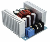
300 W synchronous buck DC-DC converter.png
 
Last edited:
Is this as simple as hooking up the input to the power supply, hooking the output to the battery, adjusting the voltage, and monitoring the current with a suitable meter? I've already got a good 20A computer server power supply that I'd sure like to get more use out of.
 
Adjust output voltage, CV control, to 3.65v before connecting to battery (as with all current limiting power supplies).

You can adjust current limit, CC control, either by shorting switcher output or after connecting to battery. This assumes you have a means to measure current like clamp on amp meter. If you don't have current meter there is a large 0.004 ohm chip resistor on back of DC-DC converter PCB board near neg output terminal you can measure voltage across. 15 amps equals 60 mV DC across this large 0.004 ohm chip resistor.

Heat sinks get too hot above 15 amps. If you run input power supply to DC-DC converter at higher input voltage there will be less current required from input power supply but DC-DC converter will run a little bit hotter. You can power three of these (three times 15A @ 3.5V outputs) from a 10 amp power supply set at 18vdc for DC-DC converter input voltage. 24vdc input @ 10A, you can run four converters each with 3.5v @ 15A output. Just split up your batteries to multiple paralleled top balancing groups to load each DC-DC converter individually to give 15A distribution to fewer parallel cells, shortening charge time.

On a current limited supply, the voltage output will drop to battery voltage level when under current limiting. This is normal. Do not readjust voltage from the inital unloaded supply 3.65v setting. Make sure you use large gauge and/or short lines to avoid more then about 50 mV voltage drop from wires to batteries. If you have more voltage drop due to wires it will just take longer to fully charge to 3.65v. Do not readjust supply voltage to make up for cable voltage drop as when battery becomes fully charged, and current drops off, the voltage will rise above the desired 3.65v limit.

Don't turn input power supply off while DC-DC converter still connected to battery. Probably won't hurt anything but disconnect leads to battery first just to be safe.
 

Attachments

  • 6-40V To 1.2-36V 300W 20A DC-DC conv Schematic.pdf
    667.8 KB · Views: 52
  • Buck Switcher 15A PCB layout.pdf
    310.8 KB · Views: 44
  • Like
Reactions: JRG
These work well. The simple boost converters do too.

But for this I used my icharger x8 which was able to give me 30 amps plus the necessary configurations for charging and will keep you clear of the pitfalls people run into with cheaper units.
 
Adjust output voltage, CV control, to 3.65v before connecting to battery (as with all current limiting power supplies).

You can adjust current limit, CC control, either by shorting switcher output or after connecting to battery. This assumes you have a means to measure current like clamp on amp meter. If you don't have current meter there is a large 0.004 ohm chip resistor on back of DC-DC converter PCB board near neg output terminal you can measure voltage across. 15 amps equals 60 mV DC across this large 0.004 ohm chip resistor.

Heat sinks get too hot above 15 amps. If you run input power supply to DC-DC converter at higher input voltage there will be less current required from input power supply but DC-DC converter will run a little bit hotter. You can power three of these (three times 15A @ 3.5V outputs) from a 10 amp power supply set at 18vdc for DC-DC converter input voltage. 24vdc input @ 10A, you can run four converters each with 3.5v @ 15A output. Just split up your batteries to multiple paralleled top balancing groups to load each DC-DC converter individually to give 15A distribution to fewer parallel cells, shortening charge time.

On a current limited supply, the voltage output will drop to battery voltage level when under current limiting. This is normal. Do not readjust voltage from the inital unloaded supply 3.65v setting. Make sure you use large gauge and/or short lines to avoid more then about 50 mV voltage drop from wires to batteries. If you have more voltage drop due to wires it will just take longer to fully charge to 3.65v. Do not readjust supply voltage to make up for cable voltage drop as when battery becomes fully charged, and current drops off, the voltage will rise above the desired 3.65v limit.

Don't turn input power supply off while DC-DC converter still connected to battery. Probably won't hurt anything but disconnect leads to battery first just to be safe.


Thanks for this tip RCinFLA. I just finished top balancing a 12v - 280 ah LFP bank with a 5amp power supply and the SZBK07, which I ordered off of Amazon. It cut down my top balance time by a factor of 3x so money spent. A few observations from my experience with the SZBK07.

I could only get 12amps max out of my SZBK07. This was at 14volts. Maybe it was knock off?

The input and output terminals are tiny, so finding a ring or spade terminals that also fit larger gauge wire is a challenge. I customized a ring terminal by snipping a portion of the ring and clamping together to form a small 'spade' style connection.

The voltage adjustment is a bit sensitive, so hard to dial in exactly. Because of this - I found it best to top balance in stages - 1st with the SZBK07 until approximately 3.45v; and 2nd at a slower rate with just the power supply - manually supervised and voltage set to 3.60v - 3.65v. It took only 30 min at 5 amps from my power supply to go from 3.45v to 3.6v and complete the top balance.
 
Adjust output voltage, CV control, to 3.65v before connecting to battery (as with all current limiting power supplies).

You can adjust current limit, CC control, either by shorting switcher output or after connecting to battery. This assumes you have a means to measure current like clamp on amp meter. If you don't have current meter there is a large 0.004 ohm chip resistor on back of DC-DC converter PCB board near neg output terminal you can measure voltage across. 15 amps equals 60 mV DC across this large 0.004 ohm chip resistor.

Heat sinks get too hot above 15 amps. If you run input power supply to DC-DC converter at higher input voltage there will be less current required from input power supply but DC-DC converter will run a little bit hotter. You can power three of these (three times 15A @ 3.5V outputs) from a 10 amp power supply set at 18vdc for DC-DC converter input voltage. 24vdc input @ 10A, you can run four converters each with 3.5v @ 15A output. Just split up your batteries to multiple paralleled top balancing groups to load each DC-DC converter individually to give 15A distribution to fewer parallel cells, shortening charge time.

On a current limited supply, the voltage output will drop to battery voltage level when under current limiting. This is normal. Do not readjust voltage from the inital unloaded supply 3.65v setting. Make sure you use large gauge and/or short lines to avoid more then about 50 mV voltage drop from wires to batteries. If you have more voltage drop due to wires it will just take longer to fully charge to 3.65v. Do not readjust supply voltage to make up for cable voltage drop as when battery becomes fully charged, and current drops off, the voltage will rise above the desired 3.65v limit.

Don't turn input power supply off while DC-DC converter still connected to battery. Probably won't hurt anything but disconnect leads to battery first just to be safe.
How certain are you about the component values in the attached DC-DC schematic? I have been doing some modelling and the design would be much more conventional (and stable) if the capacitor between the comp pins 8 and 9 were 30pF rather than 300pF and if the capacitor across the feedback pot were 500pF rather than 50pF. If you are sure that your values are correct then I need to re-examine my model.
 
How certain are you about the component values in the attached DC-DC schematic? I have been doing some modelling and the design would be much more conventional (and stable) if the capacitor between the comp pins 8 and 9 were 30pF rather than 300pF and if the capacitor across the feedback pot were 500pF rather than 50pF. If you are sure that your values are correct then I need to re-examine my model.
That cap across top reference divider resistor is only for lead compensation to give switcher faster reaction to sudden surge loads. It will work with no capacitor in this location, just slower to react to sudden load. Too much capacitance here will cause voltage overshoot response to load surge. Problem is the output is adjustable so the optimum lead compension capacitor depends on output voltage setting via the top divider resistor values setting. In most cases, better to have slower reaction to surge load then high overshoot in voltage.

Do your simulations with wide sudden load current shifts at various output voltage regulation settings to check how bad overshoot voltage gets. It will be worse overshoot when output voltage is adjusted to higher voltage (high resistance value on upper divider resistor).

Compensation gets more complicated when series inductance due to output wires is added. Too much lead compensation with series inductance in output wires can result in output voltage oscillation.
 
Last edited:
I am familiar with most of the points you have made and have already included them in my thinking, although there are some useful insights that I have picked up from your answer. However, you sort of ducked my question. How sure are you about the component values? For instance someone on another blog claims to have measured the capacitor across the divider resistor as 500pF rather than 50pF and I just wanted to confirm which is correct. Of course you could both be correct with power supplies to the same nominal design from different suppliers! Did you actually remove the components and measure them?
 
Back
Top