diy solar

diy solar

ez ground mounting system

If you unplugged two strings so you have 3s2p (6 panels), how much output do you get with one covered? 5 panels? 4? 3?


Bypass diodes are what's built in to the panels, as shown in FilterGuy's picture.
Maybe you meant blocking diode (in series with the panel). I don't think those are needed, at least not for this purpose.
I changed it to blocking diode.

What I did was compare the current output simulating when one set of panels voltage was less than the others in parallel.

For example if you have 4 panel sets in parallel and then one of the panels gets shaded in it drops the voltage say from 120v to 80v in the one set.

All you do is check your output current and then unplug the panel set where on panel is shaded and then compare the output currents.

In my case it did not matter whether it was plugged in or not so I determined that the blocking diodes were not required.
 
A test I did found panel in shade (but not absolute darkness) had Voc similar to Vmp of panel in the sun.
So a shaded string wouldn't pull down voltage below Vmp, no need for blocking diode.

The reason I ask you how a 3s2p array behaves with one shaded is the MPPT algorithm might find a peak from 3s, or a lower peak from 2p2s (really one of those is 3s, but pulled well below Vmp). Or, the peaks of 3s and 2s might blend together, so only one peak for MPPT to find.

For your 3s4p with one shaded, the 3s3p peak is higher so of course MPPT stops there. Pulling down to voltage of 2s4p would be lower watts.
You could instead cover one panel each of two strings, see if you get the power of 6 panels, 8 panels, or something else.
Only some MPPT explore the entire voltage range to find a higher wattage, lower voltage peak.

I did this test with 9s2p and saw about the output of 17 panels, but I think peak of 8s and peak of 9s are close enough together.
 
I changed it to blocking diode.

What I did was compare the current output simulating when one set of panels voltage was less than the others in parallel.

For example if you have 4 panel sets in parallel and then one of the panels gets shaded in it drops the voltage say from 120v to 80v in the one set.

All you do is check your output current and then unplug the panel set where on panel is shaded and then compare the output currents.

In my case it did not matter whether it was plugged in or not so I determined that the blocking diodes were not required.
That is a good test. Thanks for reporting on it.
Others have reported that their systems work fine without the blocking diode, but your experiment proves it.

However, I don't understand why you are not getting parasitic back-current through the covered panel. Could you throw a clamp meter on one of the leads of the covered panel and see what you get?
I don't have a clamp meter. I thought the panels had some bypass diodes to prevent that.
 
However, I don't understand why you are not getting parasitic back-current through the covered panel. Could you throw a clamp meter on one of the leads of the covered panel and see what you get?

I tried that, had two panels in series in the sun, connected to one panel in a darkened room (for electroluminescent tests, see if defects became apparent.)
It took 2x Voc to push an amp or so, didn't approach Isc or Imp. The PV curve isn't as reversible as I expected.

His cover may not have blocked all light. I've found that shaded panel has Voc about equal to Vmp of panel in unshaded sunlight, so it neither sources nor sinks current in a series/parallel array. And that would be even if entire string is shaded.


The only benefit I would expect from a blocking diode is protection if the PV string is shorted (e.g. failed bypass diodes.) That is where required fuses/breakers are supposed to prevent fires. But I don't believe polarized breakers are reliable when fed backwards in that application.

With 3s4p, windwizard ought to have OCP.
anti-backfeed diodes would appear to provide protection, but aren't necessarily proven to be reliable fire protection.
Fuses are reliable. But I gotta wonder, if a PV panel had failed bypass diode, just how hot could it get without blowing proper size fuse?
 
I see you drilled holes in the posts to slid the pipes through. Seems very strong, but I would not trust my ability to line them up. Wouldnt it be easier to attach the pipes to the front of the poles with a U bracket and then cut the post after?

Maybe place a 2 x 4 block unde the pipe for extra safety support?
 
Seems very strong, but I would not trust my ability to line them up.
I am not sure how the OP did it, but I would drill the holes and line everything up before I back-filled the dirt around the posts. This lines the posts up with the pipes instead of trying to line the pipes up with the posts.
 
But I don't believe polarized breakers are reliable when fed backwards in that application.
If polarized breakers are used for PV string protection, they should be set up as if the panels on the string being protected are the loads, not the source.

1647710306730.png
 
I am not sure how the OP did it, but I would drill the holes and line everything up before I back-filled the dirt around the posts. This lines the posts up with the pipes instead of trying to line the pipes up with the posts.
My worry, minor, is that 1 or more posts might be suspended off the bottom the hole, and the cement won't flow under, allowing the post to settle later
(edit) Probably solved by some rebar through the bottom of each post to embed in the cement.
 
My worry, minor, is that 1 or more posts might be suspended off the bottom the hole, and the cement won't flow under, allowing the post to settle later
(edit) Probably solved by some rebar through the bottom of each post to embed in the cement.
When putting posts in the ground, it is best to have the post sticking out of the bottom of the concrete in order to let moisture drain out the bottom. If the concrete is deeper than the post, it forms a cup that holds moisture and encourages rot.

1) Remove all loose soil from the hole. (Loose soil can later compact and cause issues)
2) Before putting in the concrete, put in gravel to a few inches above the bottom of the post and make sure to tap it in and under the post.
3) Pour the concrete to fill the hole.

BTW: I think the OP said he did not use concrete. He just backfield with dirt. Since all the posts are connected together with the metal racking system, there should be little or no forces to make the posts lean (they are all holding each other up). Consequently, it probably works well to forgo the concrete, but I would do my best to compact the soil as I back-filled.
 
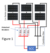
If polarized breakers are used for PV string protection, they should be set up as if the panels on the string being protected are the loads, not the source.

That would protect if one string shorted.

Now what if wire to SCC shorts. For instance, you wire it reverse polarity, so Isc flows through polarity-confusion diode (which we hope SCC has.)
Breaker doesn't trip, because Isc < breaker rating.
But now you manually turn off the breaker ...
 
When putting posts in the ground, it is best to have the post sticking out of the bottom of the concrete in order to let moisture drain out the bottom. If the concrete is deeper than the post, it forms a cup that holds moisture and encourages rot.

For a pipe frame forming trusses, so no torsion on pipes, this could be the best way to go.

For a single-pipe mount, torsion strength is required. You could pour concrete into the pipe, making a composite that is much more resistant to bending. I did this to thin-wall 1.5" chain link fence posts when I added an array against a fence.
 
That would protect if one string shorted.

Now what if wire to SCC shorts. For instance, you wire it reverse polarity, so Isc flows through polarity-confusion diode (which we hope SCC has.)
Breaker doesn't trip, because Isc < breaker rating.
But now you manually turn off the breaker ...

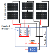
PV panels are current limited devices and proper system design takes advantage of this. The proper wire sizing for a PV circuit is such that a short anywhere on the output circuit will not cause a fire. (This is the magic 1.56 multiplier used on the PV current to select wire size). The short shown below might get warm or even hot, but will not cause a fire.

1647715246056.png

However, the panels and required wire sizes for the strings are not designed to safely handle the back-current of 2 or more strings as well as its own current. Consequently, if there is a short on the string, an OCPD is needed to shut off the current from the other strings.

 
PV panels are current limited devices and proper system design takes advantage of this. The proper wire sizing for a PV circuit is such that a short anywhere on the output circuit will not cause a fire. (This is the magic 1.56 multiplier used on the PV current to select wire size). The short shown below might get warm or even hot, but will not cause a fire.


However, the panels and required wire sizes for the strings are not designed to safely handle the back-current of 2 or more strings as well as its own current. Consequently, if there is a short on the string, an OCPD is needed to shut off the current from the other strings.


Yes, and your backwards-installed polarized breaker suggestion takes care of functioning as OCP in the event a PV string is shorted.

Although, I'm not sure shorted bypass diodes can carry enough current to trip the breaker without overheating and becoming a fire hazard.
How much do you want to bet UL listing was achieved backfeeding a panel with the current of its fuse rating, but not backfeeding a panel with failed diode? We've seen photos of PV panels with diodes failed due to shade; I expect backfeed to cause similar overheating.

Now that you've found a way to use polarized breaker for OCP of a shorted string, what happens if you close breaker into a shorted SCC (the reverse polarity connection I proposed, which many people have done)?
I think nothing. until you open the breaker. You're then interrupting Isc and letting voltage rise to Voc. In the wrong direction across a polarized breaker. I think the breaker catches fire. ?
I am not following the scenario you are trying to describe.

1647724912977.png
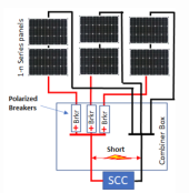
The short I show is the same as a shorted SCC. It will sit there and get hot but not burn
Open one of the breakers and the current reduces. Still no fire

If the SCC shorts internally in a way that causes a fire, I don't think *anything* done with breakers or fuses can fix the problem without having popped fuses/breakers during normal operation.

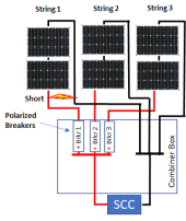
Now let's look at a short on one of the strings

1647725460547.png

If properly sized, breaker 1 will pop. The short will still carry the current from string 1, but if the wires are sized to handle 1.55 times the short circuit current, the wire will not burn
 
I am not following the scenario you are trying to describe.


The short I show is the same as a shorted SCC. It will sit there and get hot but not burn
Open one of the breakers and the current reduces. Still no fire

If the SCC shorts internally in a way that causes a fire, I don't think *anything* done with breakers or fuses can fix the problem without having popped fuses/breakers during normal operation.

Just as you show.
If the SCC has a diode to clamp reverse voltage from PV (many do), then when you close the breakers, PV panels see a short circuit and deliver Isc.
Problem is, when you manually open the breakers (they won't trip, no overload), you're now opening a polarized breaker with wrong polarity voltage and current. It will burn.

My proposed solutions:
1) Use non-polarized breakers
2) Use anti-backfeed diodes (although I am not sure they are reliable enough for fire protection.)
3) Gang all breakers together (and use in normal forward direction.) Manually opened, they are rated to interrupt the current. Backfeeding into a shorted string, the overloaded back-fed breaker trips, but can't interrupt reverse current itself. Because it is ganged to ALL the others, they turn off and interrupt the current.

All (3) should take is a pin through the handles.
Some Midnight boxes have up to 6 adjacent breakers. That works. Some have two sets of 6, separated by a lug. That won't work feeding a single MPPT input, would be OK if each (ganged) bank of 6 breakers is a separate circuit, feeding separate MPPT.
 
Problem is, when you manually open the breakers (they won't trip, no overload), you're now opening a polarized breaker with wrong polarity voltage and current. It will burn.
Will it? Why? I was not aware opening a polarized breaker with a back-feed current would cause a problem. (I am not arguing... I want to learn)
My proposed solutions:
1) Use non-polarized breakers
That certainly prevents opening a 'back-fed' breaker because there is no backward direction.
2) Use anti-backfeed diodes (although I am not sure they are reliable enough for fire protection.)
That seems like a waste of a little power if they are not otherwise needed. If polarized breakers won't work, I would find non-polarized breakers before I tried to use diodes.
3) Gang all breakers together (and use in normal forward direction.) Manually opened, they are rated to interrupt the current. Backfeeding into a shorted string, the overloaded back-fed breaker trips, but can't interrupt reverse current itself. Because it is ganged to ALL the others, they turn off and interrupt the current.
I am lost again.... if it is a polarized breaker, how would back-feeding trip it?

Also, breakers that are designed to be ganged together also have a limit on how many can be ganged. (Trying to turn off 5 or 6 back-fed breakers would probably take more force than the tripping breaker can create.
 
I do have an Outback 6-gang 15A 100V (per pole) breaker. It's purpose was to segment a 600Voc string into 6, 100Voc sub-strings.
I intend to repurpose it for parallel strings (feeding DC coupled SCC for Sunny Island). I think SunPower 435W 1s6p array would fit within specs. At the moment, I have SunPower 327W 2s1p hooked up.

Various breakers trip based on thermal, magnetic, or remote trip. (often a couple of those.)
I suppose a magnetic trip breaker might or might not trip with reverse current, depending on whether the trip mechanism itself is polarized.
The main deal with polarized breakers is they use a permanent magnet to establish a field that deflects arc into arc chutes. Reverse polarity, and that doesn't happen.
I think non-polarized DC breakers might use an electromagnet to deflect the arc.

Here's Midnight's story of they first time they tried to put polarized breakers through NRTL testing (but backwards), resulting in burning breakers:

 
Back
Top