diy solar

diy solar

Fail Safe BMS?

Mcgivor

Solar Enthusiast
Joined
Jul 24, 2021
Messages
187
The purpose of creating this thread is to discuss the weaknesses of direct FET based BMS control and ways to overcome them using alternate methods, some of which can be addressed by currently available passive BMS's but not entirely

Having collective input towads a common goal is the focus, those who are satisfied with the level of protection their FET BMS offers and see no need to improve don't need to justify their choice by including their rationale to prove a point, everyone is entitled to their respective opinion, but all too often the opinions unrelated to the subject tends to steer discussion of topic.

The FET based BMS is a device many trust to protect their system from the various conditions that could be harmful, for the most part do an excellent job but they have a fundamental flaw, there is never a physical disconnect, they often reconnect automatically to what may have caused the problem in the first place. So many failures can be attributed to such devices, wether caused by the device itself or other externally connected device failure exceeding it's limitations.

Regardless of type, the only time a BMS should intervene in a solar application is when one or more measured parameters is exceeded, the safest means to isolate the battery is physically disconnect from the offending input or output,. To prevent endless reset failure loop manifestation, having a manual reset would be benificial in establishing a fail safe system, a nessersary inconvenience.

To achieve this with a FET BMS, the output would need to drive an external no resetting relay(s), this would in many cases eliminate some features, such as overcurrent and short circuit protection for example however these can be done externally, albeit with added complexity..

This is in the thought stage, those interested in this concept are most welcome to add comments or ask questions, I'll take some time to think and produce a drawing which I'll post later. This thread is in response to a discussion that began within another thread but off topic, so a little premature.
 
I've often wondered about the viability of just running a high current rated DC contactor in place of the BMS itself. The BMS would still be hooked up but the only load through it would be the coil of the contactor.

Of course this gets in the way of the BMS detection of how much power has been through the battery but a shunt can do that.

Since I've spent exactly zero time testing such a thing I can't of course say if it'll work out or not.
 
I've often wondered about the viability of just running a high current rated DC contactor in place of the BMS itself. The BMS would still be hooked up but the only load through it would be the coil of the contactor.

There are many BMS that use this method, i have used 3 different ones with no issues (Batrium/REC/Zeva)

I wouldn’t rely on a FET based BMS for any high current application.
 
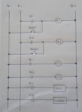
This is a first draft diagram using a common port FET BMS, being it's the most commonly used, I've purposely left out OCP devices indicator lights, buzzers etcetera for clarity.

With this method the only current the BMS has to handle are what the relays R1 & R2 consume, small DPST are all that is required so a few mA each, the contactors C1 & C2 are slave driven by through NO contacts of R1 & R2 respectively.

The relay coils of R1 & R2 are held over their own NO contact, when the BMS detects a fault, in the battery it cuts power to its P- thus dropping the relays, should the BMS restore itself R1 & R2 will not pick up until a reset is performed and can only be restored if the BMS is satisfied.

Although there is still a physical connection, the current value passing through the FET's is miniscule, not making it a true fail safe but relitivly close,
this arrangement would also allow a small capacity BMS to protect and control a significantly higher current, as the contactors now govern the maximum current.

Please forgive the hand drawn diagram, I only use a tablet which has limitations.

Thoughts,, comments and questions.20210816_153714-1.jpg
 
There are many BMS that use this method, i have used 3 different ones with no issues (Batrium/REC/Zeva)

I wouldn’t rely on a FET based BMS for any high current application.
Thanks for the input, I guess Chargery could be added to the list as it's a passive BMS with external drive outputs, making them fail safe is much the same but better because there is no electronic connection.
 
Anyone looking for an example of what uses Relays / Contactors for High Loads, look at any EV. Also note that very few are Energy Savers as such. Panasonic provides them for GM, Ford, Tesla some to VW but I believe they are also using Bosch... be seated if you look at pricing.
 
There are many BMS that use this method, i have used 3 different ones with no issues (Batrium/REC/Zeva)

I wouldn’t rely on a FET based BMS for any high current application.
Yeah I'm aware of that, I was simply wondering about doing this with a bms that isn't explicitly designed for it. If the BMS is expecting to see a certain minimum current for example, if it even bothers to measure that in the first place.

Are there BMS designs out there which have auto shutoffs based on usage to worry about that might stick it in "storage" mode unprompted?

I've very little bms experience so I can only ask.
 
I have thought of doing something like this. I would be looking at the cheap < $20 BMS which isn't smart and doesn't do any current monitoring.
In your drawing it appears both relays are connected the same way, which would not differentiate charging and discharge bus. The charge relay coil needs to be connected the the charge buss and p-, and the load relay coil to B+ and p-. That way, if the BMS turns off the load, the charge relay can still be active.

The drawing would be much easier to follow if you used standard symbols. It isn't clear what the capacitor symbol is used for. I assume in one case it is a coil, and the other a contact? And I am confused with the R and C in circles that is in series with the capacitor symbols.
 
I like the idea of a failsafe bms.

my idea is 3 levels of control
normal events
1. data communication control​
loads, charge sources and monitors can subscribe for events that they are interested in.​
2. low current signalling relays​
control loads and sources that support or can be hacked for this type of control​
abnormal events
3. high current shunt trip or similar​
with optional administrative reset​
 
Last edited:
I have thought of doing something like this. I would be looking at the cheap < $20 BMS which isn't smart and doesn't do any current monitoring.
In your drawing it appears both relays are connected the same way, which would not differentiate charging and discharge bus. The charge relay coil needs to be connected the the charge buss and p-, and the load relay coil to B+ and p-. That way, if the BMS turns off the load, the charge relay can still be active.

The drawing would be much easier to follow if you used standard symbols. It isn't clear what the capacitor symbol is used for. I assume in one case it is a coil, and the other a contact? And I am confused with the R and C in circles that is in series with the capacitor symbols.
The diagram is a simple ladder diagram not an electronic schematic, sorry for the confusion, the parrallel vertical lines are normally open contacts, labeled with the relay or contactor they're associated with, circles with a letter and number represent coils, R for relay, C for contactor,, the two dots with a bar above are push buttons, the rectangles are self explanatory. I will update with a legend.

Ladder diagrams makes for a less confusing layout to follow, which is commonly used in control wiring. Again sorry for the confusion.
 
I like the idea of a failsafe bms.

my idea is 3 levels of control
normal events
1. data communication control​
loads, charge sources and monitors can subscribe for events that they are interested in.​
2. low current signalling relays​
control loads and sources that support or can be hacked for this type of control​
abnormal events
3. high current shunt trip or similar​
with optional administrative reset​
Actually the purpose is to design a simple non auto resetting failure mode, to prevent battery damage should the operator either be away, or asleep when an event occurs, this would allow the operator to evaluate the system before deciding to reconnect ,rather than returning to a pile after ashes, or worse, waking up dead.

Further expansion is possible with certain systems which accommodate WIFI connected devices that could be controlled from anywhere in the world, but that would add layers of unnecessary confusion to the discussion at this point.
 
Actually the purpose is to design a simple non auto resetting failure mode, to prevent battery damage should the operator either be away, or asleep when an event occurs, this would allow the operator to evaluate the system before deciding to reconnect ,rather than returning to a pile after ashes, or worse, waking up dead.
That is administrative reset.
 
Back
Top